

-
Products
Overview Products

-
2D Cutting
-
Tube Cutting
-
3D Cutting
-
Intelligent Welding
-
Intelligent Cutting Head
-
Industrial Automation
-
Industrial Software
-
Combination
-
Combination
BOCHU New Product -
Combination
BOCHU New Product -
BOCHU New Product
-
2D Cutting Head
Tube Cutting Head
3D Cutting Head
Consumables
BOCHU New Product -
Servo
BOCHU New Product -
Industrial 4.0
-
- Support
- About
- Online Store










- Software Download
- Tutorial
- CloudNest
Ⅰ. Overview
When drawing a part, you do not need to draw the specific bevel appearance or bevel geometry. Simply draw the hole with the required dimensions, then click Add Bevel from the Compound Bevel drop-down menu on the top toolbar to apply a V, Y, X, or K bevel to the selected toolpath.
For details about Compound Bevel, see Compound Bevel.
Ⅱ. Version and Permissions
1.Version
Compound bevels can be added to existing bevels starting from 2025V2.
The following changes were introduced in 2026V1 and later:
-
-
- The former Describe the superposition process has been extracted into the dedicated Compound Bevel feature. Add Bevel now only supports Describe final shape.
- The main toolbar icon has been changed from Add Bevel to Compound Bevel.
-
To use these features, make sure your software version supports them. If you are using an earlier version, upgrade your nesting software first.
Difference between Add Bevel and Compound Bevel:
-
-
- Add Bevel: Adds a bevel based on a zero-degree reference. The resulting bevel angle is the angle you specify and is independent of any bevel already defined in the original drawing.
- Compound Bevel: Adds an additional bevel angle based on the bevel angle already recognized from the original drawing.
-
2.Permissions
-
-
-
The feature is available in TubesT Steel Structure Version, Professional Version, TubesT-H and Small Tube Professional Version. It is not supported in TubesT Lite, TubesT Small Tube, or 2-Chuck Version.
- Before using this feature, click the gear icon in the upper-left corner of the software, then go to User Settings → Machine Config and enable A axis bevel cutter. The A-axis swing limit should be configured according to your machine specifications. A typical value is 45°.
-
-

Ⅲ. How to Use
The following example shows how to add a bevel to a tube hole on a plane.
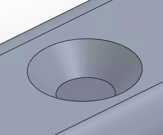
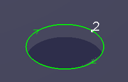
Step 1 Draw the part contour using the dimensions of a non-beveled part. The following example uses a circular hole. You can draw the hole based on either the outer contour dimensions or the inner contour dimensions.
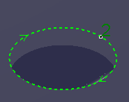
Step 2 Select the toolpath to which you want to add a bevel.
Step 3 Click Technique Setup → Compound Bevel → Add Bevel. In the Add Bevel Settings dialog box, select the required bevel type and configure the corresponding parameters.

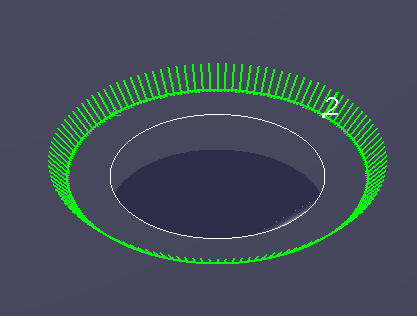
Step 4 Click OK. The software generates the corresponding bevel toolpath.
The following example shows the result after applying a Top V Bevel.
Ⅳ. Parameters for Each Bevel Type
1.Bevel Types
Based on the finished bevel profile, the available bevel types are:
-
-
- Top V Bevel
- Bottom V Bevel
- Top Y Bevel
- Bottom Y Bevel
- X Bevel
- K Bevel
-

2. Top V Bevel
Configure the bevel angle (Angle 1).
-
-
- Angle 1: The angle between the normal vector of the straight cut and the normal vector of the bevel.
- Drawing Dimensions: Specifies whether the inner contour or outer contour of the model remains unchanged.
-
-
-
-
- If the part was drawn using the outer contour dimensions, select Outer Contour.
- If the part was drawn using the inner contour dimensions, select Inner Contour.
-
-

3. Bottom V Bevel
Only the bevel angle (Angle 1) needs to be configured.
Angle 1: The angle between the toolpath tangent of the finished profile and the normal vector of the bevel.

4. Top Y Bevel
Configure the bevel angle (Angle 1) and root height (h1), as shown below.

5. Bottom Y Bevel
Configure the bevel angle (Angle 1) and root height (h1).

6.X Bevel
An X Bevel consists of two opposing bevels that form an X-shaped cross section.
Configure the following parameters:
-
-
- top bevel angle (Angle 1)
- bottom bevel angle (Angle 2)
- top bevel height (h1)
-

7. K Bevel
Configure the following parameters:
-
-
- top bevel angle (Angle 1)
- bottom bevel angle (Angle 2)
- top bevel height (h1)
- bottom bevel height (h2)
-

V. Setting the Application Scope and Path Apply Range
1.Apply to
When Current View is selected, you can apply the settings to the selected toolpaths or to all toolpaths in the current part displayed in the software interface.

When Part list is selected, you can choose specific parts or all parts from the part list on the left side of the software.

2.Select Path Apply Range
To meet different machining requirements, you can filter the target toolpaths by the following criteria:
-
-
- Cutoff Property
- Bevel Property
- Section Toolpath Type
-
These filter conditions can be used individually or in combination, allowing the settings to take effect on all toolpaths simultaneously.

Ⅰ. Overview
When drawing a part, you do not need to draw the specific bevel appearance or bevel geometry. Simply draw the hole with the required dimensions, then click Add Bevel from the Compound Bevel drop-down menu on the top toolbar to apply a V, Y, X, or K bevel to the selected toolpath.
For details about Compound Bevel, see Compound Bevel.
Ⅱ. Version and Permissions
1.Version
Compound bevels can be added to existing bevels starting from 2025V2.
The following changes were introduced in 2026V1 and later:
-
-
- The former Describe the superposition process has been extracted into the dedicated Compound Bevel feature. Add Bevel now only supports Describe final shape.
- The main toolbar icon has been changed from Add Bevel to Compound Bevel.
-
To use these features, make sure your software version supports them. If you are using an earlier version, upgrade your nesting software first.
Difference between Add Bevel and Compound Bevel:
-
-
- Add Bevel: Adds a bevel based on a zero-degree reference. The resulting bevel angle is the angle you specify and is independent of any bevel already defined in the original drawing.
- Compound Bevel: Adds an additional bevel angle based on the bevel angle already recognized from the original drawing.
-
2.Permissions
-
-
-
The feature is available in TubesT Steel Structure Version, Professional Version, TubesT-H and Small Tube Professional Version. It is not supported in TubesT Lite, TubesT Small Tube, or 2-Chuck Version.
- Before using this feature, click the gear icon in the upper-left corner of the software, then go to User Settings → Machine Config and enable A axis bevel cutter. The A-axis swing limit should be configured according to your machine specifications. A typical value is 45°.
-
-
Ⅲ. How to Use
The following example shows how to add a bevel to a tube hole on a plane.
Step 1 Draw the part contour using the dimensions of a non-beveled part. The following example uses a circular hole. You can draw the hole based on either the outer contour dimensions or the inner contour dimensions.
Step 2 Select the toolpath to which you want to add a bevel.
Step 3 Click Technique Setup → Compound Bevel → Add Bevel. In the Add Bevel Settings dialog box, select the required bevel type and configure the corresponding parameters.
Step 4 Click OK. The software generates the corresponding bevel toolpath.
The following example shows the result after applying a Top V Bevel.
Ⅳ. Parameters for Each Bevel Type
1.Bevel Types
Based on the finished bevel profile, the available bevel types are:
-
-
- Top V Bevel
- Bottom V Bevel
- Top Y Bevel
- Bottom Y Bevel
- X Bevel
- K Bevel
-
2. Top V Bevel
Configure the bevel angle (Angle 1).
-
-
- Angle 1: The angle between the normal vector of the straight cut and the normal vector of the bevel.
- Drawing Dimensions: Specifies whether the inner contour or outer contour of the model remains unchanged.
-
-
-
-
- If the part was drawn using the outer contour dimensions, select Outer Contour.
- If the part was drawn using the inner contour dimensions, select Inner Contour.
-
-
3. Bottom V Bevel
Only the bevel angle (Angle 1) needs to be configured.
Angle 1: The angle between the toolpath tangent of the finished profile and the normal vector of the bevel.
4. Top Y Bevel
Configure the bevel angle (Angle 1) and root height (h1), as shown below.
5. Bottom Y Bevel
Configure the bevel angle (Angle 1) and root height (h1).
6.X Bevel
An X Bevel consists of two opposing bevels that form an X-shaped cross section.
Configure the following parameters:
-
-
- top bevel angle (Angle 1)
- bottom bevel angle (Angle 2)
- top bevel height (h1)
-
7. K Bevel
Configure the following parameters:
-
-
- top bevel angle (Angle 1)
- bottom bevel angle (Angle 2)
- top bevel height (h1)
- bottom bevel height (h2)
-
V. Setting the Application Scope and Path Apply Range
1.Apply to
When Current View is selected, you can apply the settings to the selected toolpaths or to all toolpaths in the current part displayed in the software interface.
When Part list is selected, you can choose specific parts or all parts from the part list on the left side of the software.
2.Select Path Apply Range
To meet different machining requirements, you can filter the target toolpaths by the following criteria:
-
-
- Cutoff Property
- Bevel Property
- Section Toolpath Type
-
These filter conditions can be used individually or in combination, allowing the settings to take effect on all toolpaths simultaneously.

