

-
Products
Overview Products

-
2D Cutting
-
Tube Cutting
-
3D Cutting
-
Intelligent Welding
-
Intelligent Cutting Head
-
Industrial Automation
-
Industrial Software
-
Combination
-
Combination
BOCHU New Product -
Combination
BOCHU New Product -
Controller
BOCHU New Product -
2D Cutting Head
Tube Cutting Head
3D Cutting Head
Consumables
BOCHU New Product -
Servo
BOCHU New Product -
Industrial 4.0
-
- Support
- About
- Online Store


- Software Download
- Manual
- Video
- Tutorial
I. Overview
For non-bevel cutting machines, the laser direction is perpendicular to the stretching direction of the tube. Due to this limitation, when cutting the tube at an angle, the final cut surface differs from that in the drawing, as shown in the figure below:
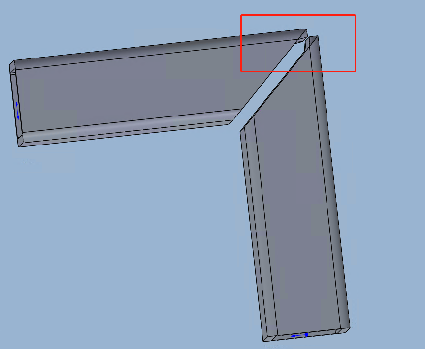
The protrusion on the wall thickness makes it impossible to successfully assemble the parts during subsequent welding. To solve this problem, it is necessary to adjust the toolpath based on the original drawing, and this adjustment method is called Weld Seam Compensation.
Note: Italic texts with blue highlights are clickable tutorial links that lead to detailed parameter explanations and usage instructions.
II. Scope of Application
1. Application
Closed tubes with inner contours and no sharp corners in the cross-section (i.e., R = 0); if there are sharp corners, they need to be rounded in advance.
Angle steel, channel steel in special toolpaths, and non-chamfered rectangular tubes that have used the 【Quick Rectangle Toolpath】 function.
2. Scenarios
-
-
- Case 1: T-joint/tilt cutting of circular tubes
-

-
-
- Case 2: Bevel cutting of angle steel, channel steel, and rectangular tubes
-
For details, please refer to 《TubesT - Toolpath Tutorial for Non-Beveling Machines: Rectangular Tubes, Angle, Channel steel》.

III. Usage
1. Adding separately to parts and toolpaths
After selecting the part and toolpath, click Weld Seam Compensation in the Technique Setup to add it.

2. Manual Batch Addition
①In the part list, select the parts that need weld compensation, right-click on the parts and click Add Weld Seam Compensation to add in batches.

②In the Weld Seam Compensation drop-down menu, select Offset All Sections.

3. Automatic Batch Addition
When you need to add Weld Seam Compensation to all imported parts in batches, check the weld compensation in 【Auto Technique】 and set the corresponding parameters.
**Notice: Enable Auto Technique first, then import the parts. If you import the parts first and then enable Auto Technique, the previously imported parts will not have weld compensation added.

Disable this when not required in case of causing errors in toolpath after importing parts
IV. FAQs
1. Can the compensation value be modified?
2. Will Weld Seam Compensation affect the length of the part?
3. How to handle the R-angle interference problem for rectangular tubes with large chamfers and thick walls?
4. What may be the reasons for the failure or ineffectiveness of weld seam compensation settings?

I. Overview
For non-bevel cutting machines, the laser direction is perpendicular to the stretching direction of the tube. Due to this limitation, when cutting the tube at an angle, the final cut surface differs from that in the drawing, as shown in the figure below:
The protrusion on the wall thickness makes it impossible to successfully assemble the parts during subsequent welding. To solve this problem, it is necessary to adjust the toolpath based on the original drawing, and this adjustment method is called Weld Seam Compensation.
Note: Italic texts with blue highlights are clickable tutorial links that lead to detailed parameter explanations and usage instructions.
II. Scope of Application
1. Application
Closed tubes with inner contours and no sharp corners in the cross-section (i.e., R = 0); if there are sharp corners, they need to be rounded in advance.
Angle steel, channel steel in special toolpaths, and non-chamfered rectangular tubes that have used the 【Quick Rectangle Toolpath】 function.
2. Scenarios
-
-
- Case 1: T-joint/tilt cutting of circular tubes
-
-
-
- Case 2: Bevel cutting of angle steel, channel steel, and rectangular tubes
-
For details, please refer to 《TubesT - Toolpath Tutorial for Non-Beveling Machines: Rectangular Tubes, Angle, Channel steel》.
III. Usage
1. Adding separately to parts and toolpaths
After selecting the part and toolpath, click Weld Seam Compensation in the Technique Setup to add it.
2. Manual Batch Addition
①In the part list, select the parts that need weld compensation, right-click on the parts and click Add Weld Seam Compensation to add in batches.
②In the Weld Seam Compensation drop-down menu, select Offset All Sections.
3. Automatic Batch Addition
When you need to add Weld Seam Compensation to all imported parts in batches, check the weld compensation in 【Auto Technique】 and set the corresponding parameters.
**Notice: Enable Auto Technique first, then import the parts. If you import the parts first and then enable Auto Technique, the previously imported parts will not have weld compensation added.
Disable this when not required in case of causing errors in toolpath after importing parts
IV. FAQs
1. Can the compensation value be modified?
2. Will Weld Seam Compensation affect the length of the part?
3. How to handle the R-angle interference problem for rectangular tubes with large chamfers and thick walls?
4. What may be the reasons for the failure or ineffectiveness of weld seam compensation settings?

