

-
Products
Overview Products

-
2D Cutting
-
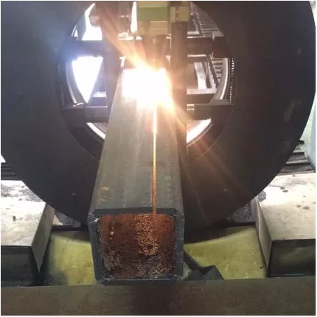
Tube Cutting
-
3D Cutting
-
Intelligent Welding
-
Intelligent Cutting Head
-
Industrial Automation
-
Industrial Software
-
Combination
-
Combination
BOCHU New Product -
Combination
BOCHU New Product -
Controller
BOCHU New Product -
2D Cutting Head
Tube Cutting Head
3D Cutting Head
Consumables
BOCHU New Product -
Servo
BOCHU New Product -
Industrial 4.0
-
- Support
- About
- Online Store


- Software Download
- Manual
- Video
- Tutorial
Ⅰ. Introduction
When identifying pipes, the software must preserve the complete cross-section. Otherwise, it cannot determine whether the pipe to be processed is a non-standard or standard pipe.
If the cross-section is damaged, the drawing must be reprocessed. Whether the part drawing format is re-editable determines the method for modifying the drawing.
★ How to determine if a part is editable? ① Check the file format (classified in the table below) ② Click the part list; if a small pencil icon appears, secondary editing is possible.

II. Navigation
This article covers numerous common scenarios.
★ You can first identify which tutorial you need based on its features, then click the corresponding link to jump directly to the relevant section.
★ After jumping, scroll up slightly with your mouse wheel to view the subheadings.
| Scenario | File Format | Object Type | Usage | Quick Jump |
| Existing drawings have been imported. |
IGS, SAT, STEP, X2T, IFC, etc. Formats that cannot be edited within the software |
Three Overall Methods |
Positioning Hole + Draw Wrap Preserve the complete cross-section using break curve Replace slots with lines |
Three Overall Methods |
|
Dividing round tubes, square tubes, etc., into regular segments
|
Positioning holes + wrapping lines
|
Case 1 | ||
|
Divide round tubes and square tubes into regular planar sections
|
Pre-draw elongated slots, then enter TubesT to replace them with lines | Case 2 | ||
|
Divide the circular tube into asymmetrical segments
|
Preserve the complete cross-section; use break curve to eliminate redundant toolpaths | Case 3 | ||
|
Slicing on square tubes with material-saving nesting
|
Preserve the full cross-section by using break curve to eliminate redundant toolpaths | Case 4 | ||
|
Cut rounded corners on square tubes
|
Preserve the full cross-section; use break curve to eliminate redundant toolpaths | Case 5 | ||
|
Cutting Small Angle Steel from Large Angle Steel 1
|
Preserve the complete cross-section; use break curve to eliminate redundant toolpaths | Case 6 | ||
|
Cutting Small Angle Steel from Large Angle Steel 2
|
Preserve the complete cross-section; use break curve to eliminate redundant toolpaths | Case 7 | ||
|
How to cut large-sized angle steel into small-sized angle steel with rounded corners |
Preserve the complete cross-section; use break curve to eliminate redundant toolpaths | Case 8 | ||
|
t2t, nc1, software internal drawing, etc. Software-editable formats |
Part Import Failed | Open in the 【Part Drawing】interface and modify the feature of the break section to a marking property. | Case 9 | |
| Newly Drawn Parts in TubesT | / | Newly Drawn Solid Parts in TubesT | Using Marking | Case 10 |
| How to Cut Large-Size Angle Steel into Smaller-Size Angle Steel with Rounded Corners | Using Marking |


III . Case Study
Three Overall Methods:
1、Positioning Hole + Draw Wrap
2、Preserve the complete cross-section using break curve
3、Replace slots with lines

Case 1: Using <Positioning Holes + Draw Wrap > to Divide Round Tubes into sheet mental parts

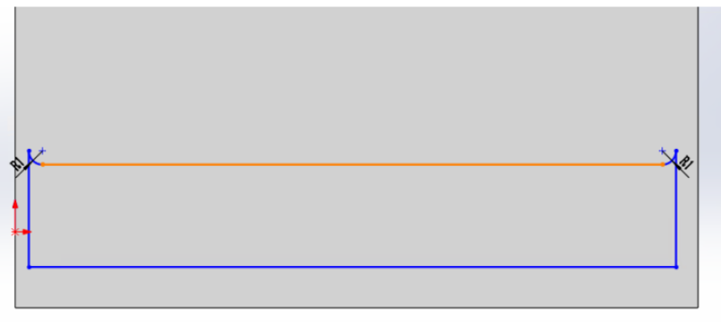
Step 1: During drawing, create small holes along the part's division line (positioning holes should be 0.1mm from the edge at the top)

Step 2: Draw the wrap line to define the required toolpath, then delete the positioning holes.


Step 3: Sort the toolpaths for individual parts. If locating holes are positioned too close to the edge, making it difficult to clamp the sliced tubes after separation, add micro-connections along the warp line.

Tutorial Video:
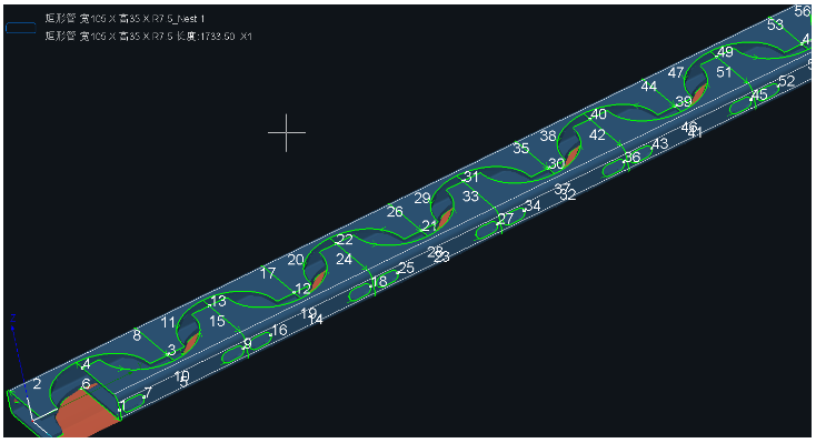
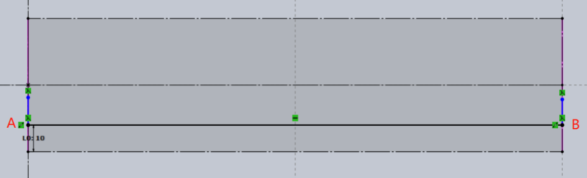
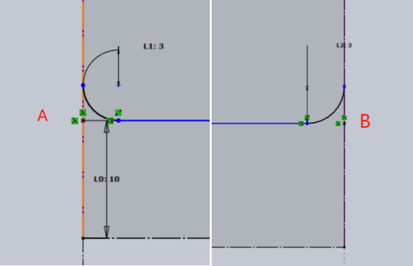
Case 2: Segmenting 400mm-long round and square tubes by drawing a thin slot in advance and replacing it with a line in TubesT
Step 1: Draw a thin slot at the division line, with both ends positioned 0.1mm from the tube ends. Note: The illustration below uses the software's internal interface as an example; the external drawing method is identical.


Step 2: After selecting the thin strip toolpath, choose 【Replace Slot with Line】 from the Curve Tool dropdown menu.

The maximum width must exceed the slot's width. For example, if the current slot width is 0.1, set it to 0.13 to convert the slot into a line.

Prior to version 1.35, you needed to use the Draw Wrap function to connect both ends of the rectangular tube.
Then delete the toolpath of the rectangular tube to achieve the effect of replacing it with a line.

Step 3: Sort toolpaths for individual parts. If the positioning holes are too close to the edge, making it difficult to clamp the sliced tubing after separation, micro-connections can be added along the wrapping line.

Tutorial Video:
Case 3: Using the method of <preserving the full cross-section + brake curve to remove redundant toolpaths>, divide the round tube into two irregular sections.

Step 1: During drawing, add 0.1mm thin sections at both ends of the part to form a complete round tube.
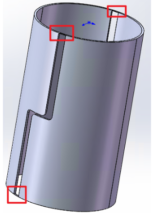
Step 2: After importing the part, retain the small cross-section with toolpaths on both sides. Use 【Break Curve 】+ 【Delete】to remove redundant toolpaths at the thin sections.
Note: Do not modify the toolpaths for the first and last cuts.
Tutorial Video:
Case 4: Preserve Full Cross-Section + use the method of【Break Curve 】to remove excess toolpaths, achieve a material-saving sheet part on a rectangular tube.

Step 1: During drawing, preserve the tube cross-section. Sketch two parts to create the desired nesting pattern.

Step 2: After importing the parts, toolpaths remain on both sides of the retained small cross-section. Use 【Break Curve 】+ 【Delete】to remove the redundant inner toolpaths.

Step 3: Reorder the toolpaths, then perform nesting and simulation. Once toolpath accuracy is confirmed, export the machining task for processing.
Video Tutorial:
Case 5: Using the method of <preserving full cross-section + break curve to eliminate redundant toolpaths>, an angle steel part is obtained from a rectangular tube (as shown in the figure).
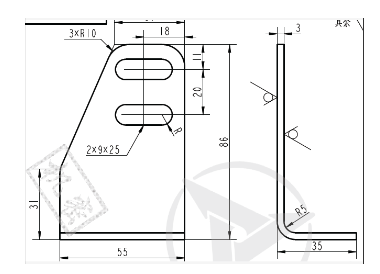
Step 1: Create the part shown below in SolidWorks. Directly sketch the desired nesting pattern on the rectangular tube instead of a single part.

Step 2: During import, select the【 In-part shape】option.

Step 3: Review toolpath sequence, nesting, simulate, and export machining files.

To minimize material usage and reduce toolpaths, you can thin the retained cross-section and use 【Break Curve】 and 【Delete】 to create the desired toolpaths.


Video Tutorial:
Case 6: Using the method of <preserving the full cross-section + Break Curve to eliminate redundant toolpaths>, cut a small filleted angle steel part from an angle steel (as shown in the figure).

Step 1: When drawing the part, preserve a small section of the pipe's cross-section.
Step 2: Import the part into TubesT. Use 【Break Curve】and 【Delete】to remove redundant toolpaths.
Step 3: Sort, nest, simulate, and export for machining.
Video tutorial:
Case 7: Using the method of <preserving the full cross-section + Break Curve to remove redundant toolpaths>, cut a small filleted angle steel part on the angle steel (as shown in the figure).

Step 1: Draw the section to be removed as a hole, positioned 0.1mm from the edge. During laser processing, 0.1mm will be precisely cut through.
Step 2: After importing the part into TubesT, use the 【Break Curve】 function to divide the complete toolpath of the hole into two segments. Retain the required toolpath and delete the redundant toolpath 0.1mm from the edge.
Video Tutorial:
Case 8: Using the method of <preserving the full cross-section + Break curve to eliminate redundant toolpaths>, cut a small angle steel part with rounded corners from an angle steel.
First, sketch the angle steel in SW using the dimensions of the existing “large-size angle steel” as parameters.
After sketching the angle steel, select the reference plane requiring dimensional modification to enter the sketch mode.
Then, draw two parallel lines and two vertical lines as shown in Figure 1. Then create fillets at points A and B to obtain Figure 2.

Next, delete the two small protruding segments above the fillet and connect the fillet to the lower parallel lines as illustrated below.
Set the distance of the section to be cut to 1mm from the edge, as 0.1mm will be precisely cut during laser processing. The configuration is shown below

After drawing, exit the sketch mode. Remove the drawn section and export the file in the correct IGES or SAT format.
Open TubesT and import the IGES or SAT file created earlier. Use the 【Break Curve】 function to retain the required toolpaths and delete the excess toolpaths within 1mm of the edge.
Video Tutorial:
Case 9: Using the <Marking> method to resolve import failures caused by incomplete part cross-sections.
When importing parts with damaged cross-sections, the software will display an import failure message.
In this case, click 【Draw Part】, then click 📂 in the upper-left corner of the drawing interface to import the surface part.


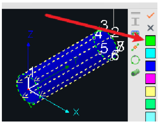
Change the tensile removal feature of the break section to 【Marking】, then click OK in the upper-right corner to import the part.


Change the marking layer (orange)to a cutting layer(green).

Case 10: Drawing Square and Round Tube Slice Parts in TubesT
(1) Use Smart Drawing to sketch a line at the desired cutting position

(2) Check the Marking Layer and configure array parameters

(3) Generate the part and switch to Layer 1
Case 11: Drawing Large-Size Angle Steel in TubesT and Cutting It into Small-Size Angle Steel with R-Corners
Enter the part drawing interface. select the main tube as the angle steel, enters the dimensions as the parameters of the existing “large-size angle steel,” and clicks Apply.
Click Smart Drawing under the branch pipe, then select the reference plane needing size reduction. Here, we use the “Top View Reference Plane” as an example.
After entering the Smart Drawing interface, draw one horizontal line and two vertical lines as shown below, positioning them to constrain the area where the angle steel needs to be reduced.
Select “Fillet,” click at points A and B, set the desired fillet radius R, then click OK. After setting, the enlarged view at points A and B appears as shown below.

Delete the two vertical line segments created in Step 1 (still blue at this point). After deletion, the enlarged views at points A and B appear as shown below.
Click OK to exit the Smart Drawing interface and enter the Part Drawing interface. In the left parameter panel, check the “Marking” option and click Apply.

After clicking OK to generate the part, select the line previously designated for marking and set its layer to match the cutting toolpath layer.
Video Tutorial:
Ⅰ. Introduction
When identifying pipes, the software must preserve the complete cross-section. Otherwise, it cannot determine whether the pipe to be processed is a non-standard or standard pipe.
If the cross-section is damaged, the drawing must be reprocessed. Whether the part drawing format is re-editable determines the method for modifying the drawing.
★ How to determine if a part is editable? ① Check the file format (classified in the table below) ② Click the part list; if a small pencil icon appears, secondary editing is possible.
II. Navigation
This article covers numerous common scenarios.
★ You can first identify which tutorial you need based on its features, then click the corresponding link to jump directly to the relevant section.
★ After jumping, scroll up slightly with your mouse wheel to view the subheadings.
| Scenario | File Format | Object Type | Usage | Quick Jump |
| Existing drawings have been imported. |
IGS, SAT, STEP, X2T, IFC, etc. Formats that cannot be edited within the software |
Three Overall Methods |
Positioning Hole + Draw Wrap Preserve the complete cross-section using break curve Replace slots with lines |
Three Overall Methods |
|
Dividing round tubes, square tubes, etc., into regular segments
|
Positioning holes + wrapping lines
|
Case 1 | ||
|
Divide round tubes and square tubes into regular planar sections
|
Pre-draw elongated slots, then enter TubesT to replace them with lines | Case 2 | ||
|
Divide the circular tube into asymmetrical segments
|
Preserve the complete cross-section; use break curve to eliminate redundant toolpaths | Case 3 | ||
|
Slicing on square tubes with material-saving nesting
|
Preserve the full cross-section by using break curve to eliminate redundant toolpaths | Case 4 | ||
|
Cut rounded corners on square tubes
|
Preserve the full cross-section; use break curve to eliminate redundant toolpaths | Case 5 | ||
|
Cutting Small Angle Steel from Large Angle Steel 1
|
Preserve the complete cross-section; use break curve to eliminate redundant toolpaths | Case 6 | ||
|
Cutting Small Angle Steel from Large Angle Steel 2
|
Preserve the complete cross-section; use break curve to eliminate redundant toolpaths | Case 7 | ||
|
How to cut large-sized angle steel into small-sized angle steel with rounded corners |
Preserve the complete cross-section; use break curve to eliminate redundant toolpaths | Case 8 | ||
|
t2t, nc1, software internal drawing, etc. Software-editable formats |
Part Import Failed | Open in the 【Part Drawing】interface and modify the feature of the break section to a marking property. | Case 9 | |
| Newly Drawn Parts in TubesT | / | Newly Drawn Solid Parts in TubesT | Using Marking | Case 10 |
| How to Cut Large-Size Angle Steel into Smaller-Size Angle Steel with Rounded Corners | Using Marking |
III . Case Study
Three Overall Methods:
1、Positioning Hole + Draw Wrap
2、Preserve the complete cross-section using break curve
3、Replace slots with lines
Case 1: Using <Positioning Holes + Draw Wrap > to Divide Round Tubes into sheet mental parts
Step 1: During drawing, create small holes along the part's division line (positioning holes should be 0.1mm from the edge at the top)
Step 2: Draw the wrap line to define the required toolpath, then delete the positioning holes.
Step 3: Sort the toolpaths for individual parts. If locating holes are positioned too close to the edge, making it difficult to clamp the sliced tubes after separation, add micro-connections along the warp line.
Tutorial Video:
Case 2: Segmenting 400mm-long round and square tubes by drawing a thin slot in advance and replacing it with a line in TubesT
Step 1: Draw a thin slot at the division line, with both ends positioned 0.1mm from the tube ends. Note: The illustration below uses the software's internal interface as an example; the external drawing method is identical.
Step 2: After selecting the thin strip toolpath, choose 【Replace Slot with Line】 from the Curve Tool dropdown menu.
The maximum width must exceed the slot's width. For example, if the current slot width is 0.1, set it to 0.13 to convert the slot into a line.
Prior to version 1.35, you needed to use the Draw Wrap function to connect both ends of the rectangular tube.
Then delete the toolpath of the rectangular tube to achieve the effect of replacing it with a line.
Step 3: Sort toolpaths for individual parts. If the positioning holes are too close to the edge, making it difficult to clamp the sliced tubing after separation, micro-connections can be added along the wrapping line.
Tutorial Video:
Case 3: Using the method of <preserving the full cross-section + brake curve to remove redundant toolpaths>, divide the round tube into two irregular sections.
Step 1: During drawing, add 0.1mm thin sections at both ends of the part to form a complete round tube.
Step 2: After importing the part, retain the small cross-section with toolpaths on both sides. Use 【Break Curve 】+ 【Delete】to remove redundant toolpaths at the thin sections.
Note: Do not modify the toolpaths for the first and last cuts.
Tutorial Video:
Case 4: Preserve Full Cross-Section + use the method of【Break Curve 】to remove excess toolpaths, achieve a material-saving sheet part on a rectangular tube.
Step 1: During drawing, preserve the tube cross-section. Sketch two parts to create the desired nesting pattern.
Step 2: After importing the parts, toolpaths remain on both sides of the retained small cross-section. Use 【Break Curve 】+ 【Delete】to remove the redundant inner toolpaths.
Step 3: Reorder the toolpaths, then perform nesting and simulation. Once toolpath accuracy is confirmed, export the machining task for processing.
Video Tutorial:
Case 5: Using the method of <preserving full cross-section + break curve to eliminate redundant toolpaths>, an angle steel part is obtained from a rectangular tube (as shown in the figure).
Step 1: Create the part shown below in SolidWorks. Directly sketch the desired nesting pattern on the rectangular tube instead of a single part.
Step 2: During import, select the【 In-part shape】option.
Step 3: Review toolpath sequence, nesting, simulate, and export machining files.
To minimize material usage and reduce toolpaths, you can thin the retained cross-section and use 【Break Curve】 and 【Delete】 to create the desired toolpaths.
Video Tutorial:
Case 6: Using the method of <preserving the full cross-section + Break Curve to eliminate redundant toolpaths>, cut a small filleted angle steel part from an angle steel (as shown in the figure).
Step 1: When drawing the part, preserve a small section of the pipe's cross-section.
Step 2: Import the part into TubesT. Use 【Break Curve】and 【Delete】to remove redundant toolpaths.
Step 3: Sort, nest, simulate, and export for machining.
Video tutorial:
Case 7: Using the method of <preserving the full cross-section + Break Curve to remove redundant toolpaths>, cut a small filleted angle steel part on the angle steel (as shown in the figure).
Step 1: Draw the section to be removed as a hole, positioned 0.1mm from the edge. During laser processing, 0.1mm will be precisely cut through.
Step 2: After importing the part into TubesT, use the 【Break Curve】 function to divide the complete toolpath of the hole into two segments. Retain the required toolpath and delete the redundant toolpath 0.1mm from the edge.
Video Tutorial:
Case 8: Using the method of <preserving the full cross-section + Break curve to eliminate redundant toolpaths>, cut a small angle steel part with rounded corners from an angle steel.
First, sketch the angle steel in SW using the dimensions of the existing “large-size angle steel” as parameters.
After sketching the angle steel, select the reference plane requiring dimensional modification to enter the sketch mode.
Then, draw two parallel lines and two vertical lines as shown in Figure 1. Then create fillets at points A and B to obtain Figure 2.
Next, delete the two small protruding segments above the fillet and connect the fillet to the lower parallel lines as illustrated below.
Set the distance of the section to be cut to 1mm from the edge, as 0.1mm will be precisely cut during laser processing. The configuration is shown below
After drawing, exit the sketch mode. Remove the drawn section and export the file in the correct IGES or SAT format.
Open TubesT and import the IGES or SAT file created earlier. Use the 【Break Curve】 function to retain the required toolpaths and delete the excess toolpaths within 1mm of the edge.
Video Tutorial:
Case 9: Using the <Marking> method to resolve import failures caused by incomplete part cross-sections.
When importing parts with damaged cross-sections, the software will display an import failure message.
In this case, click 【Draw Part】, then click 📂 in the upper-left corner of the drawing interface to import the surface part.
Change the tensile removal feature of the break section to 【Marking】, then click OK in the upper-right corner to import the part.
Change the marking layer (orange)to a cutting layer(green).
Case 10: Drawing Square and Round Tube Slice Parts in TubesT
(1) Use Smart Drawing to sketch a line at the desired cutting position
(2) Check the Marking Layer and configure array parameters
(3) Generate the part and switch to Layer 1
Case 11: Drawing Large-Size Angle Steel in TubesT and Cutting It into Small-Size Angle Steel with R-Corners
Enter the part drawing interface. select the main tube as the angle steel, enters the dimensions as the parameters of the existing “large-size angle steel,” and clicks Apply.
Click Smart Drawing under the branch pipe, then select the reference plane needing size reduction. Here, we use the “Top View Reference Plane” as an example.
After entering the Smart Drawing interface, draw one horizontal line and two vertical lines as shown below, positioning them to constrain the area where the angle steel needs to be reduced.
Select “Fillet,” click at points A and B, set the desired fillet radius R, then click OK. After setting, the enlarged view at points A and B appears as shown below.
Delete the two vertical line segments created in Step 1 (still blue at this point). After deletion, the enlarged views at points A and B appear as shown below.
Click OK to exit the Smart Drawing interface and enter the Part Drawing interface. In the left parameter panel, check the “Marking” option and click Apply.
After clicking OK to generate the part, select the line previously designated for marking and set its layer to match the cutting toolpath layer.
Video Tutorial:

