

-
Products
Overview Products

-
2D Cutting
-
Tube Cutting
-
3D Cutting
-
Intelligent Welding
-
Intelligent Cutting Head
-
Industrial Automation
-
Industrial Software
-
Combination
-
Combination
BOCHU New Product -
Combination
BOCHU New Product -
Controller
BOCHU New Product -
2D Cutting Head
Tube Cutting Head
3D Cutting Head
Consumables
BOCHU New Product -
Servo
BOCHU New Product -
Industrial 4.0
-
- Support
- About
- Online Store


- Software Download
- Manual
- Video
- Tutorial
I. Introduction
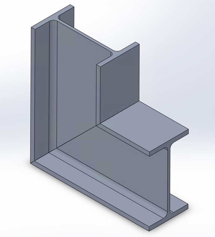
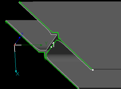
When the laser cutting machine is not a bevelling model, it will not be able to cut the bevel above the wall thickness of the pipe because the cutting head cannot be deflected and always keep the light out vertically.

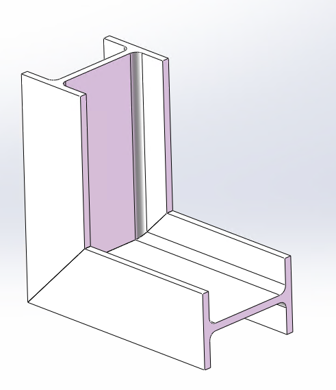
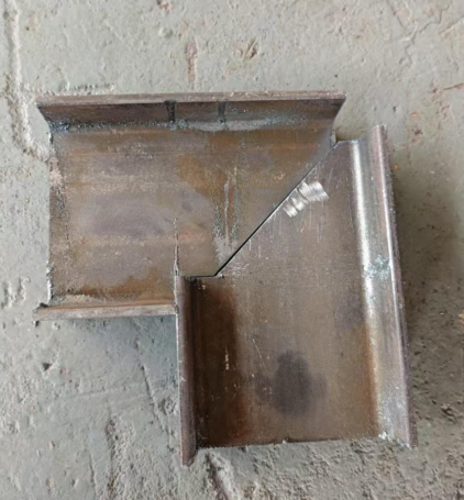
For the two L-shaped splicing method I-beams pictured below, if they are cut by a non-bevelling machine, there will be a problem with the wing and web knife paths not connecting to each other, resulting in the parts not falling naturally.
Note: Italic texts with blue highlights are clickable tutorial links that lead to detailed parameter explanations and usage instructions.
II. Solutions
Various cases and treatment ideas
For this kind of problem, there are different ways to deal with oblique cut in different directions, depending on the desired part effect.
You can first according to the effect of the programme, choose what you need tutorials, directly click on the corresponding link, quickly jump to the desired location.
★ Jump after the mouse in the scroll wheel slide up a little to see the sub-title.
| Types of oblique cut | Treatment ideas | Effects | Solutions | Quickly jump |
|
X-directional oblique cut
Toolpaths are generated according to the contour of the part: less material on the concave side, more material on the protruding side, and no toolpath continuity.
|
Consider whether you need more or less material at the flange panels
Less material: there are missing corners that can be welded in.
More material: need to sand off the excess.
|
Less material on the concave side, more material on the protruding side, and toolpath continuity.
|
Use of the 【Optimizaze H - beam web toolpath】 Batch and automatic toolpath processing |
Solution 1 |
|
More or Less material on both sides, and toolpath continuity.
|
Manual modification of drawings Flexibility to modify multiple styles |
Solution 2 | ||
|
Z-directional oblique cut
Toolpaths are generated according to the contour of the part: More material if the web plate is downhill at the time of import, less material if the web plate is uphill, and possibly no toolpath continuity
|
Consider whether you need more or less material at the web panels
Less material: there are missing corners that can be welded in.
More material: need to sand off the excess.
|
Web plate free to switch between more/less material
|
Part Rotation 、Reverse, and use 【Quick Rectangle Toolpath】 | Solution 3 |
|
Web plate more/less material, toolpath continuity
|
Use of the 【Optimizaze H - beam web toolpath】 Batch and automatic toolpath processing |
Solution 4 | ||
|
More or Less material on both plate, toolpath continuity
|
Manual modification of drawings |
Solution 5 |


Ⅲ. Detailed Steps
1、X-directional oblique cut
(1)Less material on the concave side, more on the convex side, and ensure toolpath continuity.

① Import the part and perform 【Collision-Avoid】. Then click 【Optimizaze H - beam web toolpath】.
Note: The 【Optimizaze H - beam web toolpath】function is exclusive to the structural steel version. If you do not see it in the toolbar, please first refer to the guide on 【 How to obtain the steel structure package and enable steel structure】.

② Set the parameters as shown in the figure. Once completed, click OK.

(2)Less or more material on both side, and toolpath continuity.


① Draw a straight-cut H-beam and import it into the software. Perform toolpath collision detection.
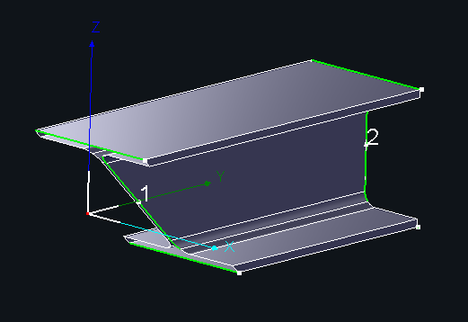
② Use the 【Measure】 tool → from the drop-down, select 【Display Normal Vector】. Measure the Z-direction distance from the B-axis start rotation point to the outer surface of the flange.
③ Based on the measured value, draw the male and female ends.
Note: The drawing examples below are shown using TubesT, but you can also use external software such as SolidWorks.
-
-
- Video Tutorial – Drawing Male ends
-
-
-
- Video Tutorial – Drawing Female ends
-
After processing the parts according to the above method, the subsequent parts can be realised with an effect similar to the ‘male-female joint’.
In addition, the outside of the splice can be drawn in the shape of a notch, creating the effect of ‘outer less material, inner male and female’.
2、Z-directional oblique cut
(1)Web plate free to switch between more/less material

① Select the part and click Reverse/Rotate.
② Select the toolpath/part you want to change, then go to 【Curve Tools】 → 【Quick Rectangle Toolpath】.
③ Video tutorial
(2)Less or more material on web plate, and toolpath continuity.


① Import the part and perform 【Collision-Avoid】, then click 【Optimizaze H - beam web toolpath】.
Note: The 【Optimizaze H - beam web toolpath】function is exclusive to the structural steel version. If you do not see it in the toolbar, please first refer to the guide on 【how to Activate Structural Steel Permissions】.

② Set the parameters as shown in the figure. Once completed, click OK.

(3)More or Less material on both plate, toolpath continuity
Instead of cutting the web diagonally, draw a right triangle shape and use extrusion cut to make a vertical cut on the web.
① Draw a straight-cut H-beam and import it into the software.
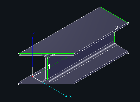
② Measure the distance between the two 45° chamfered edges.

③Drawing
Note: The following tutorial is an example of drawing in TubesT. However, in practice, you can draw in TubesT as well as in external software such as SolidWorks.
Step 1: Draw a trapezoid where the slanted edge is at a 45° angle to the horizontal.
Step 2: Activate the Intersection Point command, and click the center reference line and the slanted edge to create an intersection.

Step 3: Activate the Perpendicular Bisector command, and click three points in sequence (order matters!).

Step 4: Set the position:
①The base of the isosceles triangle should be slightly longer than the measured value (e.g., use 16.7 mm).
②Confirm the part’s total length.
Step 5: Trim unnecessary segments.

Step 6: Apply the Branch Pipe Tool, then generate the part.
④Video Tutorial:
note that the first step of the measurement should be taken from the end of the web on the side with the toolpath, pulling horizontally to the side without the toolpath, as detailed in step 1 above
I. Introduction
When the laser cutting machine is not a bevelling model, it will not be able to cut the bevel above the wall thickness of the pipe because the cutting head cannot be deflected and always keep the light out vertically.
For the two L-shaped splicing method I-beams pictured below, if they are cut by a non-bevelling machine, there will be a problem with the wing and web knife paths not connecting to each other, resulting in the parts not falling naturally.
Note: Italic texts with blue highlights are clickable tutorial links that lead to detailed parameter explanations and usage instructions.
II. Solutions
Various cases and treatment ideas
For this kind of problem, there are different ways to deal with oblique cut in different directions, depending on the desired part effect.
You can first according to the effect of the programme, choose what you need tutorials, directly click on the corresponding link, quickly jump to the desired location.
★ Jump after the mouse in the scroll wheel slide up a little to see the sub-title.
| Types of oblique cut | Treatment ideas | Effects | Solutions | Quickly jump |
|
X-directional oblique cut
Toolpaths are generated according to the contour of the part: less material on the concave side, more material on the protruding side, and no toolpath continuity.
|
Consider whether you need more or less material at the flange panels
Less material: there are missing corners that can be welded in.
More material: need to sand off the excess.
|
Less material on the concave side, more material on the protruding side, and toolpath continuity.
|
Use of the 【Optimizaze H - beam web toolpath】 Batch and automatic toolpath processing |
Solution 1 |
|
More or Less material on both sides, and toolpath continuity.
|
Manual modification of drawings Flexibility to modify multiple styles |
Solution 2 | ||
|
Z-directional oblique cut
Toolpaths are generated according to the contour of the part: More material if the web plate is downhill at the time of import, less material if the web plate is uphill, and possibly no toolpath continuity
|
Consider whether you need more or less material at the web panels
Less material: there are missing corners that can be welded in.
More material: need to sand off the excess.
|
Web plate free to switch between more/less material
|
Part Rotation 、Reverse, and use 【Quick Rectangle Toolpath】 | Solution 3 |
|
Web plate more/less material, toolpath continuity
|
Use of the 【Optimizaze H - beam web toolpath】 Batch and automatic toolpath processing |
Solution 4 | ||
|
More or Less material on both plate, toolpath continuity
|
Manual modification of drawings |
Solution 5 |
Ⅲ. Detailed Steps
1、X-directional oblique cut
(1)Less material on the concave side, more on the convex side, and ensure toolpath continuity.
① Import the part and perform 【Collision-Avoid】. Then click 【Optimizaze H - beam web toolpath】.
Note: The 【Optimizaze H - beam web toolpath】function is exclusive to the structural steel version. If you do not see it in the toolbar, please first refer to the guide on 【 How to obtain the steel structure package and enable steel structure】.
② Set the parameters as shown in the figure. Once completed, click OK.
(2)Less or more material on both side, and toolpath continuity.
① Draw a straight-cut H-beam and import it into the software. Perform toolpath collision detection.
② Use the 【Measure】 tool → from the drop-down, select 【Display Normal Vector】. Measure the Z-direction distance from the B-axis start rotation point to the outer surface of the flange.
③ Based on the measured value, draw the male and female ends.
Note: The drawing examples below are shown using TubesT, but you can also use external software such as SolidWorks.
-
-
- Video Tutorial – Drawing Male ends
-
-
-
- Video Tutorial – Drawing Female ends
-
After processing the parts according to the above method, the subsequent parts can be realised with an effect similar to the ‘male-female joint’.
In addition, the outside of the splice can be drawn in the shape of a notch, creating the effect of ‘outer less material, inner male and female’.
2、Z-directional oblique cut
(1)Web plate free to switch between more/less material
① Select the part and click Reverse/Rotate.
② Select the toolpath/part you want to change, then go to 【Curve Tools】 → 【Quick Rectangle Toolpath】.
③ Video tutorial
(2)Less or more material on web plate, and toolpath continuity.
① Import the part and perform 【Collision-Avoid】, then click 【Optimizaze H - beam web toolpath】.
Note: The 【Optimizaze H - beam web toolpath】function is exclusive to the structural steel version. If you do not see it in the toolbar, please first refer to the guide on 【how to Activate Structural Steel Permissions】.
② Set the parameters as shown in the figure. Once completed, click OK.
(3)More or Less material on both plate, toolpath continuity
Instead of cutting the web diagonally, draw a right triangle shape and use extrusion cut to make a vertical cut on the web.
① Draw a straight-cut H-beam and import it into the software.
② Measure the distance between the two 45° chamfered edges.
③Drawing
Note: The following tutorial is an example of drawing in TubesT. However, in practice, you can draw in TubesT as well as in external software such as SolidWorks.
Step 1: Draw a trapezoid where the slanted edge is at a 45° angle to the horizontal.
Step 2: Activate the Intersection Point command, and click the center reference line and the slanted edge to create an intersection.
Step 3: Activate the Perpendicular Bisector command, and click three points in sequence (order matters!).
Step 4: Set the position:
①The base of the isosceles triangle should be slightly longer than the measured value (e.g., use 16.7 mm).
②Confirm the part’s total length.
Step 5: Trim unnecessary segments.
Step 6: Apply the Branch Pipe Tool, then generate the part.
④Video Tutorial:
note that the first step of the measurement should be taken from the end of the web on the side with the toolpath, pulling horizontally to the side without the toolpath, as detailed in step 1 above

