

-
Products
Overview Products

-
2D Cutting
-
Tube Cutting
-
3D Cutting
-
Intelligent Welding
-
Intelligent Cutting Head
-
Industrial Automation
-
Industrial Software
-
Combination
-
Combination
BOCHU New Product -
Combination
BOCHU New Product -
Controller
BOCHU New Product -
2D Cutting Head
Tube Cutting Head
3D Cutting Head
Consumables
BOCHU New Product -
Servo
BOCHU New Product -
Industrial 4.0
-
- Support
- About
- Online Store


- Software Download
- Manual
- Video
- Tutorial
Ⅰ. Introduction
When the software identifies tubing, the part must retain its complete cross-section; otherwise, it cannot determine which tube the sheet metal part will be machined onto.
For instance, the sheet-body shown below could be cut from a rectangular tube or a non-rectangular profile.

Therefore, when the part drawing is a sheet metal part, the original tube's complete cross-section must be preserved to enable the software to identify and confirm the tube type.

Note: The content in 【】or [] is all tutorial links that can be jumped to. Clicking the link allows you to view the detailed parameter description and usage method corresponding to the function.
II. Foundational General Knowledge
Before starting the operation, please make sure you have read the 【What is TubesT?】 and understand the role of the nesting software in the entire processing flow, as well as the usage methods of various file formats and the meanings of version types.
| Scenario | Configuration Method |
|
If you are using a pipe cutting machine and are in the steel construction industry, you must enable steel construction permissions. The structural steel machine is automatically enabled; you may ignore this step. If not enabled, you may encounter situations where the features mentioned below are not visible in your software interface! |
【How to obtain the steel structure package and enable steel structure】 |
| Non-beveling models need not check this option; related functions will automatically hide for a cleaner interface. | 【How to enable beveling】 |
| To enable backup of nesting files, allowing re-editing toolpaths if processing errors are discovered during actual machining. | 【Save YXY Files】 |
III. The Nesting Process
1. Pre-Process and Auto Technique
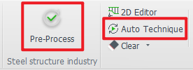
There are some common operations, such as:
Automatically adding marking text to parts (recommended)
Familiar with some basic processes, want the software to automatically add leader lines and compensation to tube holes (recommended)
For features you're highly familiar with and commonly use in your industry—such as weld compensation and intersect holes—you may want the software to handle them automatically (on demand).
You can configure these settings in advance under 【Auto Process】 before importing parts. The software will then execute the operations automatically during part import.
★ After importing parts, you only need to review them—no manual setup required. This significantly boosts nesting efficiency.
★ If you notice unusual toolpaths or undesired results after importing parts, check whether any unnecessary automatic processes are enabled.
2. Drafting Parts and Toolpath Processing
Whether parts can be re-edited within the software determines how drawings are processed. For specific methods, refer to the 【Tutorial on Toolpath Processing for Sheet Metal Parts】
★ If prompted with “Performing <Normal Vector Error Detection>” after drawing or importing a bevel part, click OK.
This function checks bevel toolpaths for recognized bevel parts. Parts with obvious errors will be flagged with a small yellow triangle.
If errors appear, refer to the 【Normal Vector Error Detection】tutorial for resolution. Non-bevel machines may ignore this step.

3. Check the Mark
If you need to mark part numbers on components, please verify the marking text position after toolpath processing:
When evenly dividing a tube into multiple sections, ensure marking text is added to each section;
When actual cutting involves both scrap and usable parts, check whether the text is positioned on the scrap or the usable section.
To delete text, select it and press the keyboard's Delete key. To add text, refer to the 【Add Text on Tubes】 guide.
4. Nest
After parts inspection is complete, nest can proceed. The figure below provides a functional overview. For detailed parameter specifications and usage instructions, refer to 【Apply Auto Nest】.

| Normal Parameters | Meaning |
| Dead Zone |
Pipe Cutter: For zero-offcut laser machine, set directly to 0; for non-zero-offcut laser machine, enter the machine's offcut length. Consult equipment after-sales for specific parameters. Shape Steel Machine: Set directly to 0; |
| Front Margin |
The uncut section at the front of the pipe (typically used when burrs are present; requires pairing with the “One-Click Align Pipe Ends” function in cutting software) |
| Loop Nesting |
Essential for Steel Structure Users:【Loop Nesting】 Note: Parts with cutting/marking lines spanning the entire component may fail to cut through. |
| Other Special Settings |
【Place Short Parts at Tail End】, 【Place Long Parts at Tail End】, 【Straight Cut End Position】 |
5. Auto Sort and Inspection
Note: After manually adding marking text, even if the toolpath has been inspected for a single part, you must re-sort it again!!
Sorting parameters can be selected as needed. For detailed parameter explanations, see: 【Auto Sort】.

6. Toolpath Check
After parts are sorted, path inspection can be performed. The software will pop up warnings for toolpaths that may pose risks. — For detailed instructions, refer to【Check Path 】

7. Simulate
Regardless of whether modifications were made based on the path check prompts, simulation must be performed.
| Method | Effect | Tutorial |
|
Click Simulation
|
Simulate actual machining conditions
|
【Simulation】 |
|
Manual Preview
|
First click on a blank area (i.e., the black background), then click the arrow in the image. The toolpath to be machined will be highlighted in blue. With multiple clicks, the software will sequentially highlight the toolpaths to be machined in blue according to the actual cutting order. After machining, they will display in yellow.
|
/ |


8. Export Task Package
After sorting the nesting layout, you can export the nesting results. For detailed instructions, refer to【Export】.
You can also export the nesting report. For detailed instructions, refer to: 【Nest Report】.

Ⅰ. Introduction
When the software identifies tubing, the part must retain its complete cross-section; otherwise, it cannot determine which tube the sheet metal part will be machined onto.
For instance, the sheet-body shown below could be cut from a rectangular tube or a non-rectangular profile.
Therefore, when the part drawing is a sheet metal part, the original tube's complete cross-section must be preserved to enable the software to identify and confirm the tube type.
Note: The content in 【】or [] is all tutorial links that can be jumped to. Clicking the link allows you to view the detailed parameter description and usage method corresponding to the function.
II. Foundational General Knowledge
Before starting the operation, please make sure you have read the 【What is TubesT?】 and understand the role of the nesting software in the entire processing flow, as well as the usage methods of various file formats and the meanings of version types.
| Scenario | Configuration Method |
|
If you are using a pipe cutting machine and are in the steel construction industry, you must enable steel construction permissions. The structural steel machine is automatically enabled; you may ignore this step. If not enabled, you may encounter situations where the features mentioned below are not visible in your software interface! |
【How to obtain the steel structure package and enable steel structure】 |
| Non-beveling models need not check this option; related functions will automatically hide for a cleaner interface. | 【How to enable beveling】 |
| To enable backup of nesting files, allowing re-editing toolpaths if processing errors are discovered during actual machining. | 【Save YXY Files】 |
III. The Nesting Process
1. Pre-Process and Auto Technique
There are some common operations, such as:
Automatically adding marking text to parts (recommended)
Familiar with some basic processes, want the software to automatically add leader lines and compensation to tube holes (recommended)
For features you're highly familiar with and commonly use in your industry—such as weld compensation and intersect holes—you may want the software to handle them automatically (on demand).
You can configure these settings in advance under 【Auto Process】 before importing parts. The software will then execute the operations automatically during part import.
★ After importing parts, you only need to review them—no manual setup required. This significantly boosts nesting efficiency.
★ If you notice unusual toolpaths or undesired results after importing parts, check whether any unnecessary automatic processes are enabled.
2. Drafting Parts and Toolpath Processing
Whether parts can be re-edited within the software determines how drawings are processed. For specific methods, refer to the 【Tutorial on Toolpath Processing for Sheet Metal Parts】
★ If prompted with “Performing <Normal Vector Error Detection>” after drawing or importing a bevel part, click OK.
This function checks bevel toolpaths for recognized bevel parts. Parts with obvious errors will be flagged with a small yellow triangle.
If errors appear, refer to the 【Normal Vector Error Detection】tutorial for resolution. Non-bevel machines may ignore this step.
3. Check the Mark
If you need to mark part numbers on components, please verify the marking text position after toolpath processing:
When evenly dividing a tube into multiple sections, ensure marking text is added to each section;
When actual cutting involves both scrap and usable parts, check whether the text is positioned on the scrap or the usable section.
To delete text, select it and press the keyboard's Delete key. To add text, refer to the 【Add Text on Tubes】 guide.
4. Nest
After parts inspection is complete, nest can proceed. The figure below provides a functional overview. For detailed parameter specifications and usage instructions, refer to 【Apply Auto Nest】.
| Normal Parameters | Meaning |
| Dead Zone |
Pipe Cutter: For zero-offcut laser machine, set directly to 0; for non-zero-offcut laser machine, enter the machine's offcut length. Consult equipment after-sales for specific parameters. Shape Steel Machine: Set directly to 0; |
| Front Margin |
The uncut section at the front of the pipe (typically used when burrs are present; requires pairing with the “One-Click Align Pipe Ends” function in cutting software) |
| Loop Nesting |
Essential for Steel Structure Users:【Loop Nesting】 Note: Parts with cutting/marking lines spanning the entire component may fail to cut through. |
| Other Special Settings |
【Place Short Parts at Tail End】, 【Place Long Parts at Tail End】, 【Straight Cut End Position】 |
5. Auto Sort and Inspection
Note: After manually adding marking text, even if the toolpath has been inspected for a single part, you must re-sort it again!!
Sorting parameters can be selected as needed. For detailed parameter explanations, see: 【Auto Sort】.
6. Toolpath Check
After parts are sorted, path inspection can be performed. The software will pop up warnings for toolpaths that may pose risks. — For detailed instructions, refer to【Check Path 】
7. Simulate
Regardless of whether modifications were made based on the path check prompts, simulation must be performed.
| Method | Effect | Tutorial |
|
Click Simulation
|
Simulate actual machining conditions
|
【Simulation】 |
|
Manual Preview
|
First click on a blank area (i.e., the black background), then click the arrow in the image. The toolpath to be machined will be highlighted in blue. With multiple clicks, the software will sequentially highlight the toolpaths to be machined in blue according to the actual cutting order. After machining, they will display in yellow.
|
/ |
8. Export Task Package
After sorting the nesting layout, you can export the nesting results. For detailed instructions, refer to【Export】.
You can also export the nesting report. For detailed instructions, refer to: 【Nest Report】.

