

-
Products
Overview Products

-
2D Cutting
-
Tube Cutting
-
3D Cutting
-
Intelligent Welding
-
Intelligent Cutting Head
-
Industrial Automation
-
Industrial Software
-
Combination
-
Combination
BOCHU New Product -
Combination
BOCHU New Product -
Controller
BOCHU New Product -
2D Cutting Head
Tube Cutting Head
3D Cutting Head
Consumables
BOCHU New Product -
Servo
BOCHU New Product -
Industrial 4.0
-
- Support
- About
- Online Store


- Software Download
- Manual
- Video
- Tutorial
Ⅰ. Introduction
How to clamp shaped tubes? How to modify toolpaths after importing shaped tubes? What to do when uneven wall thickness prevents cutting? What to do when the cutting head hits the tube wall at recessed corners?
Before processing parts, read this tutorial to help you nest more efficiently!
Note: The content in 【】or [] in blue is all tutorial links that can be jumped to. Clicking the link allows you to view the detailed parameter description and usage method corresponding to the function.
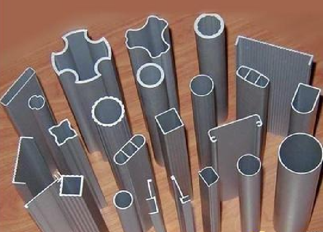
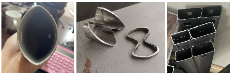
Closed-section shaped tubes
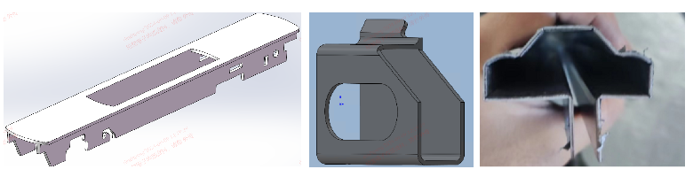
Open-section shaped tubes
II. Foundational General Knowledge
Before starting the operation, please make sure you have read the 【What is TubesT?】 and understand the role of the nesting software in the entire processing flow, as well as the usage methods of various file formats and the meanings of version types.
| Scenario | Configuration Method |
|
If you are using a pipe cutting machine and are in the steel construction industry, you must enable steel construction permissions. The structural steel machine is automatically enabled; you may ignore this step. If not enabled, you may encounter situations where the features mentioned below are not visible in your software interface! |
【How to obtain the steel structure package and enable steel structure】 |
|
If you are using a beveling machine, you need to enable beveling. If not enabled, you may encounter situations where the features mentioned below are not visible in your software interface! Non-beveling models need not check this option; related functions will automatically hide for a cleaner interface. |
【How to enable beveling】 |
| Parts with identical cross-sectional dimensions but varying thicknesses should be arranged on pipes of corresponding thicknesses. | |
| To enable backup of nesting files, allowing re-editing toolpaths if processing errors are discovered during actual machining. | |
| Automatically merge parts with identical cross-sectional dimensions but different drawing file names into a single part. |
【Merge identical parts】 |
III. The Nesting Process
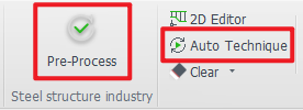
1. Pre-Process and Auto Technique
There are some common operations, such as:
Automatically adding marking text to parts (recommended)
Familiar with some basic processes, want the software to automatically add leader lines and compensation to tube holes (recommended)
For features you're highly familiar with and commonly use in your industry—such as weld compensation and intersect holes—you may want the software to handle them automatically (on demand).
You can configure these settings in advance under 【Auto Process】 before importing parts. The software will then execute the operations automatically during part import.
★ After importing parts, you only need to review them—no manual setup required. This significantly boosts nesting efficiency.
★ If you notice unusual toolpaths or undesired results after importing parts, check whether any unnecessary automatic processes are enabled.
2. Get the parts
| Source | Format | Tutorials (Mandatory to Watch) |
|
SolidWorks、ug and etc.
|
igs, sat, step and etc. |
|
|
TubesT - TubeDraw
|
jhb, jhbs and etc. |
|
|
crafts
|
dxf |


★ If the import fails, you can troubleshoot it based on these experiences: 【How to Resolve Part Import Failed or Recognition Errors】
★ If part names and file names don't match after importing, refer to:【Using File Names for Imported Parts】
★ For parts of identical dimensions that are identified as two different sizes due to minor dimensional variations, preventing placement on the same pipe, and when you do not wish to redraw the design, refer to【Nest Parts with Similar Dimension】
Note: Significant errors require redrawing according to specifications!
3. Check the Parts
Before part processing, inspect parts to prevent post-nesting discrepancies. Reprocessing erroneous parts consumes significant additional time. Refer to the following checklist:
① Marking
-
-
-
- Is marking text applied?
- Is positioning appropriate?
-
-
② Bevel Integrity Check (For beveled parts)
-
-
-
- Are all bevels correctly identified?
- Does the bevel toolpath achieve intended results?
-
-
③ Toolpath Anomaly Detection
-
-
-
- Missing toolpaths?
- Redundant/extra toolpaths?
-
-
★ If a prompt appears after import: "Normal Vector Error Check", click "OK".
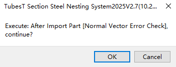
This feature performs toolpath verification on parts identified with bevels. Components containing critical errors will be flagged with yellow warning triangles.
If errors are detected, resolve them by referring to "【Normal Vector Error Detection】
4. Rotating profile
The actual clamping orientation on the chuck must match the profile preview in the upper-left corner of the software.
For example, with the shaped pipe shown below, the default straight edge faces upward upon import. The chuck should also clamp with the straight edge facing upward.

If creating a dedicated fixture for a specific profile pipe to ensure consistent orientation during clamping, and requiring a particular surface of the drawing to face upward, refer to the tutorial【Rotating profile】
After clamping the pipe with the fixture, the profile pipe stands upright. If the orientation of the pipe in the drawing is not altered, you must manually rotate the B-axis 90° before each machining operation and then set the current orientation to horizontal.
5. Custom Profile Toolpath Contour
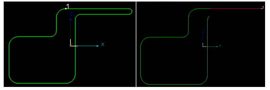
After importing parts, issues such as redundant toolpaths may arise. For example: generating double-layer toolpaths (left image below) when a single layer would suffice for cutting (right image below). In such cases, toolpath editing is required.
Additionally, shaped tubes often exhibit uneven wall thickness at corners. When editing toolpaths, layers must be replaced for sections with inconsistent wall thickness. This means freely determining whether to differentiate processes based on the actual part conditions.
Approach: First, remove duplicate cutting paths. Next,
Procedure: Enter Custom Profile Toolpath Contour→ Curve Split → Delete Duplicate Toolpaths → Split Layers at Corner Wall Thicknesses → Adjust Toolpath Sequence → Apply to All Sections with Identical Cross-Sections.
Detailed Analysis of Multiple Cases: 【Custom Profile Toolpath Contour for Shaped Tube】
6. Modify Contour Vector
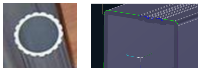
The cutting head may experience collisions at recessed corners. Before nesting, edit the 【Contour Vector】; starting from version 7.1.57.1, this function has been upgraded to 【Toolpath Collision Avoidance】.
For shaped tubes with recessed corners, failure to perform toolpath collision detection before cutting may result in cutting head collisions during operation.

After performing collision prevention, the normal vectors at corners will be adjusted. The cutting results are shown in the figure below:

Tutorial Video:
When automatic modification fails, or when a cutting head model is missing and automatic modification is impossible, use 【Manual Contour Vector Modification】.

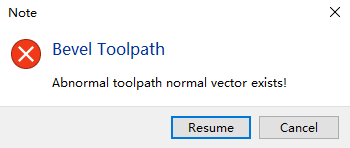
Note: When machining non-chamfered shaped tubes, if normal vectors abruptly change at corners, use 【Smooth Contour Vector】 within 【Manual Contour Vector Modification】 to modify the abrupt vector changes.

7. For certain special shaped tubes
① Shaped tubes with curved grooves in the cross-section: Follow-cut by editing the contour vector.

② Special-shaped tubes with small steps in cross-section: Switch cutting layers and set fixed-height cutting in Tubupro.
③ Special-shaped tubes with reinforcing ribs: The [Saw Cut Line] feature added in version 7.1.41 and later can be used with sawing machines to cut tubes with reinforcing ribs.
Laser cutting effect for special-shaped tubes with reinforcing ribs:
Set saw cut effect:
8.Auto-Nest
After completing part inspection, proceed to nesting operations.Reference Tutorial: 【Apply Auto Nest】.
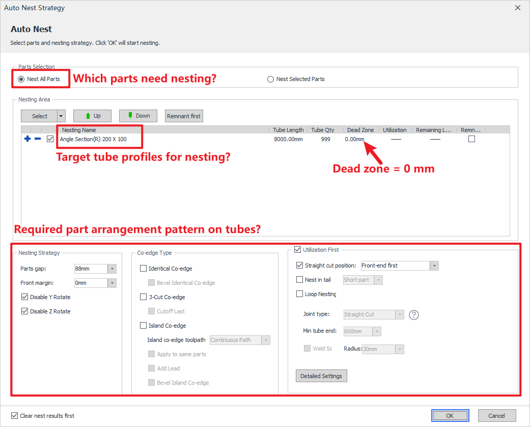
| Common Parameters | Definitions |
| Dead Zone |
The parameter can be directly set to 0 as the default configuration. For special processing requirements, users may manually adjust the parameter value. |
| Front margin |
The parameter can be directly set to 0 as the default configuration. |
| ★ Loop Nesting★ | Core Principle of Nesting. The tutorial is mandatory viewing for all operators. |
| Other Special Settings |
Straight cut position |
★ There are special requirements for the layout. The automatic nest does not meet my expectations. Can I arrange it manually? — Use the 【Manual nest】 feature. However, it is recommended to check the layout parameters first.
9. Auto Sort and Inspection
After part nesting, sorting can proceed. Sorting will comprehensively consider machining efficiency to rationally sequence each toolpath. — For detailed instructions, refer to:
S For detailed parameter explanations, see: 【Auto Sort】.

10. Toolpath Check (optional)
After parts are sorted, path inspection can be performed. The software will pop up warnings for toolpaths that may pose risks. — For detailed instructions, refer to【Check Path 】

11. Export Task Package
After sorting the nesting layout, you can export the nesting results. For detailed instructions, refer to【Export】
You can also export the nesting report. For detailed instructions, refer to: 【Nest Report】.

IV. FAQs for cutting issues
| Step | Questions | Function |
|
Step 1: Import the machining file |
Can't open the machining file? Toolpath display error? |
The nesting software version must match the cutting software version. |
| Step 2: Load the material | After loading the profile tube, the chuck's clamping state must match the status displayed in the TubesT part preview interface. |
【Rotating profile】 |
| Step 3: Set the process | Due to the numerous corners on profile tubes and thicker wall sections in certain recesses, achieving thorough penetration at corners requires configuring distinct machining processes for these areas. |
Modify Layers:
Enable Corner Technique in Cutting Software:
|
| Step 4: Set the centering |
Center-finding configuration Pre-machining center-finding: Center-finding measures deviations caused by misalignment between the clamped tube's center and the B-axis center, compensating during machining to ensure precision. Therefore, center-finding must be performed before machining to guarantee cutting accuracy. Mid-Process Centering: To guarantee the accuracy of hole positions on the tube surface, mid-process centering can be configured. |
Center-Finding Configuration: 【Center-Finding Methods Summary】、【Non-Standard Pipe Center-Finding Methods Summary】、【Manual Centering】、【Advanced Manual Center-Finding】 Center-Finding During Machining: 【Center-Finding During Machining】 |
| Step 5: Perform a run dry before machining. | Performing a dry run before machining allows verification of the cutting trajectory's feasibility, prevents the cutting head from missing the target, and avoids collisions, thereby enhancing cutting safety! |  |


Ⅰ. Introduction
How to clamp shaped tubes? How to modify toolpaths after importing shaped tubes? What to do when uneven wall thickness prevents cutting? What to do when the cutting head hits the tube wall at recessed corners?
Before processing parts, read this tutorial to help you nest more efficiently!
Note: The content in 【】or [] in blue is all tutorial links that can be jumped to. Clicking the link allows you to view the detailed parameter description and usage method corresponding to the function.
Closed-section shaped tubes
Open-section shaped tubes
II. Foundational General Knowledge
Before starting the operation, please make sure you have read the 【What is TubesT?】 and understand the role of the nesting software in the entire processing flow, as well as the usage methods of various file formats and the meanings of version types.
| Scenario | Configuration Method |
|
If you are using a pipe cutting machine and are in the steel construction industry, you must enable steel construction permissions. The structural steel machine is automatically enabled; you may ignore this step. If not enabled, you may encounter situations where the features mentioned below are not visible in your software interface! |
【How to obtain the steel structure package and enable steel structure】 |
|
If you are using a beveling machine, you need to enable beveling. If not enabled, you may encounter situations where the features mentioned below are not visible in your software interface! Non-beveling models need not check this option; related functions will automatically hide for a cleaner interface. |
【How to enable beveling】 |
| Parts with identical cross-sectional dimensions but varying thicknesses should be arranged on pipes of corresponding thicknesses. | |
| To enable backup of nesting files, allowing re-editing toolpaths if processing errors are discovered during actual machining. | |
| Automatically merge parts with identical cross-sectional dimensions but different drawing file names into a single part. |
【Merge identical parts】 |
III. The Nesting Process
1. Pre-Process and Auto Technique
There are some common operations, such as:
Automatically adding marking text to parts (recommended)
Familiar with some basic processes, want the software to automatically add leader lines and compensation to tube holes (recommended)
For features you're highly familiar with and commonly use in your industry—such as weld compensation and intersect holes—you may want the software to handle them automatically (on demand).
You can configure these settings in advance under 【Auto Process】 before importing parts. The software will then execute the operations automatically during part import.
★ After importing parts, you only need to review them—no manual setup required. This significantly boosts nesting efficiency.
★ If you notice unusual toolpaths or undesired results after importing parts, check whether any unnecessary automatic processes are enabled.
2. Get the parts
| Source | Format | Tutorials (Mandatory to Watch) |
|
SolidWorks、ug and etc.
|
igs, sat, step and etc. |
|
|
TubesT - TubeDraw
|
jhb, jhbs and etc. |
|
|
crafts
|
dxf |
★ If the import fails, you can troubleshoot it based on these experiences: 【How to Resolve Part Import Failed or Recognition Errors】
★ If part names and file names don't match after importing, refer to:【Using File Names for Imported Parts】
★ For parts of identical dimensions that are identified as two different sizes due to minor dimensional variations, preventing placement on the same pipe, and when you do not wish to redraw the design, refer to【Nest Parts with Similar Dimension】
Note: Significant errors require redrawing according to specifications!
3. Check the Parts
Before part processing, inspect parts to prevent post-nesting discrepancies. Reprocessing erroneous parts consumes significant additional time. Refer to the following checklist:
① Marking
-
-
-
- Is marking text applied?
- Is positioning appropriate?
-
-
② Bevel Integrity Check (For beveled parts)
-
-
-
- Are all bevels correctly identified?
- Does the bevel toolpath achieve intended results?
-
-
③ Toolpath Anomaly Detection
-
-
-
- Missing toolpaths?
- Redundant/extra toolpaths?
-
-
★ If a prompt appears after import: "Normal Vector Error Check", click "OK".
This feature performs toolpath verification on parts identified with bevels. Components containing critical errors will be flagged with yellow warning triangles.
If errors are detected, resolve them by referring to "【Normal Vector Error Detection】
4. Rotating profile
The actual clamping orientation on the chuck must match the profile preview in the upper-left corner of the software.
For example, with the shaped pipe shown below, the default straight edge faces upward upon import. The chuck should also clamp with the straight edge facing upward.
If creating a dedicated fixture for a specific profile pipe to ensure consistent orientation during clamping, and requiring a particular surface of the drawing to face upward, refer to the tutorial【Rotating profile】
After clamping the pipe with the fixture, the profile pipe stands upright. If the orientation of the pipe in the drawing is not altered, you must manually rotate the B-axis 90° before each machining operation and then set the current orientation to horizontal.
5. Custom Profile Toolpath Contour
After importing parts, issues such as redundant toolpaths may arise. For example: generating double-layer toolpaths (left image below) when a single layer would suffice for cutting (right image below). In such cases, toolpath editing is required.
Additionally, shaped tubes often exhibit uneven wall thickness at corners. When editing toolpaths, layers must be replaced for sections with inconsistent wall thickness. This means freely determining whether to differentiate processes based on the actual part conditions.
Approach: First, remove duplicate cutting paths. Next,
Procedure: Enter Custom Profile Toolpath Contour→ Curve Split → Delete Duplicate Toolpaths → Split Layers at Corner Wall Thicknesses → Adjust Toolpath Sequence → Apply to All Sections with Identical Cross-Sections.
Detailed Analysis of Multiple Cases: 【Custom Profile Toolpath Contour for Shaped Tube】
6. Modify Contour Vector
The cutting head may experience collisions at recessed corners. Before nesting, edit the 【Contour Vector】; starting from version 7.1.57.1, this function has been upgraded to 【Toolpath Collision Avoidance】.
For shaped tubes with recessed corners, failure to perform toolpath collision detection before cutting may result in cutting head collisions during operation.
After performing collision prevention, the normal vectors at corners will be adjusted. The cutting results are shown in the figure below:
Tutorial Video:
When automatic modification fails, or when a cutting head model is missing and automatic modification is impossible, use 【Manual Contour Vector Modification】.
Note: When machining non-chamfered shaped tubes, if normal vectors abruptly change at corners, use 【Smooth Contour Vector】 within 【Manual Contour Vector Modification】 to modify the abrupt vector changes.
7. For certain special shaped tubes
① Shaped tubes with curved grooves in the cross-section: Follow-cut by editing the contour vector.
② Special-shaped tubes with small steps in cross-section: Switch cutting layers and set fixed-height cutting in Tubupro.
③ Special-shaped tubes with reinforcing ribs: The [Saw Cut Line] feature added in version 7.1.41 and later can be used with sawing machines to cut tubes with reinforcing ribs.
Laser cutting effect for special-shaped tubes with reinforcing ribs:
Set saw cut effect:
8.Auto-Nest
After completing part inspection, proceed to nesting operations.Reference Tutorial: 【Apply Auto Nest】.
| Common Parameters | Definitions |
| Dead Zone |
The parameter can be directly set to 0 as the default configuration. For special processing requirements, users may manually adjust the parameter value. |
| Front margin |
The parameter can be directly set to 0 as the default configuration. |
| ★ Loop Nesting★ | Core Principle of Nesting. The tutorial is mandatory viewing for all operators. |
| Other Special Settings |
Straight cut position |
★ There are special requirements for the layout. The automatic nest does not meet my expectations. Can I arrange it manually? — Use the 【Manual nest】 feature. However, it is recommended to check the layout parameters first.
9. Auto Sort and Inspection
After part nesting, sorting can proceed. Sorting will comprehensively consider machining efficiency to rationally sequence each toolpath. — For detailed instructions, refer to:
S For detailed parameter explanations, see: 【Auto Sort】.
10. Toolpath Check (optional)
After parts are sorted, path inspection can be performed. The software will pop up warnings for toolpaths that may pose risks. — For detailed instructions, refer to【Check Path 】
11. Export Task Package
After sorting the nesting layout, you can export the nesting results. For detailed instructions, refer to【Export】
You can also export the nesting report. For detailed instructions, refer to: 【Nest Report】.
IV. FAQs for cutting issues
| Step | Questions | Function |
|
Step 1: Import the machining file |
Can't open the machining file? Toolpath display error? |
The nesting software version must match the cutting software version. |
| Step 2: Load the material | After loading the profile tube, the chuck's clamping state must match the status displayed in the TubesT part preview interface. |
【Rotating profile】 |
| Step 3: Set the process | Due to the numerous corners on profile tubes and thicker wall sections in certain recesses, achieving thorough penetration at corners requires configuring distinct machining processes for these areas. |
Modify Layers:
Enable Corner Technique in Cutting Software:
|
| Step 4: Set the centering |
Center-finding configuration Pre-machining center-finding: Center-finding measures deviations caused by misalignment between the clamped tube's center and the B-axis center, compensating during machining to ensure precision. Therefore, center-finding must be performed before machining to guarantee cutting accuracy. Mid-Process Centering: To guarantee the accuracy of hole positions on the tube surface, mid-process centering can be configured. |
Center-Finding Configuration: 【Center-Finding Methods Summary】、【Non-Standard Pipe Center-Finding Methods Summary】、【Manual Centering】、【Advanced Manual Center-Finding】 Center-Finding During Machining: 【Center-Finding During Machining】 |
| Step 5: Perform a run dry before machining. | Performing a dry run before machining allows verification of the cutting trajectory's feasibility, prevents the cutting head from missing the target, and avoids collisions, thereby enhancing cutting safety! | |

