

-
Products
Overview Products

-
2D Cutting
-
Tube Cutting
-
3D Cutting
-
Intelligent Welding
-
Intelligent Cutting Head
-
Industrial Automation
-
Industrial Software
-
Combination
-
Combination
BOCHU New Product -
Combination
BOCHU New Product -
Controller
BOCHU New Product -
2D Cutting Head
Tube Cutting Head
3D Cutting Head
Consumables
BOCHU New Product -
Servo
BOCHU New Product -
Industrial 4.0
-
- Support
- About
- Online Store


- Software Download
- Manual
- Video
- Tutorial
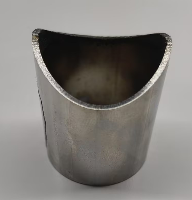
Ⅰ. Overview
When processing parts that require bevel cutting (with the A-axis swinging during machining), and the drawing already shows the bevel shape, the bevel must be recognized during import.
Notice:
-
-
- If the actual machine tool is not a bevel machine, do not recognize the bevel, as it will make machining impossible.
- If the drawing does not show the bevel to be machined, it can be used 【Add Bevel】.
-

-
-
- The content in blue are clickable tutorial links. Click the link to view detailed parameter descriptions and usage methods for the corresponding functions.
-
Ⅱ. Function Description
1.Enable Bevel
Before using this function, click the small gear icon in the upper-left corner of the software, go to 【User Settings→Machine Config】, and check 【Bevel Cutting Head】.
A-axis swing angle limit: Recommended 45°. The maximum swing angle of the a-axis on the machine tool is ±45°. If different, confirm with the equipment manufacturer and enter the actual value.
A-axis swing length: Measures the swing length on the machine tool and enter the actual/approximate value. This value is only for correct display during simulation and does not affect actual nesting or processing.

2.Check Bevel during Import
Recognize Bevel: For part drawings created in external software, the bevel needs to be recognized first. In the parameter settings of Import from File , check Bevel. The bevel toolpath of the imported part will then match the bevel in the drawing.
Version impact:
-
-
-
- After version 7.1.61 (i.e. 2025v1), bevel can be recognized for all formats except *.sat. Files in *.step format are recommended.
- Before version 7.1.59, files in *.igs format are recommended.
-
-

3.Automatic Normal Vector Detection after Import
★ If a prompt appears after import which is about to perform Normal Vector Error Check, click OK.
If no prompt appears, you may configure based on the tutorial Normal Vector Error Check.
This will check the bevel toolpath of the imported files. And the error will be marked with a yellow triangle if there is an exception.

4. If Normal Vector Detection Finds Errors

The software will display a "small triangle exclamation mark" to locate: ① the part in the part list; ② the specific toolpath with the issue.
Hover the mouse over the "small triangle exclamation mark" to see the specific cause of the toolpath vector error.

If prompted "Part toolpath has overswing angle": Use 【Overswing Angle Handling】 to process the part.
If prompted Abnormal toolpath normal vector exists and the part is a closed section (such as square tubes or round tubes), check the prompted part in the part list, click 【Cancel Bevel】, then click 【Scan Bevel】 to batch re-recognize the bevel.

Supplementary notice on the Scan Bevel function: Scan Bevel is another method to recognize bevels, achieving the same result—recognizing the bevel angle. It differs only in the underlying method, so use it to re-recognize when issues occur.
Usage: Select the toolpath or part and click 【Scan Bevel】.
5. If errors persist and Scan Bevel cannot resolve them, or the part is an open section
① Turn on <Display Normal Vectors> to view the toolpath with the "small triangle exclamation mark" and check where the vector is incorrect.
② After locating the abnormal vector, verify if the drawing at this position is correctly drawn.
③ If the drawing is incorrect, modify it; if correct, ask the group owner in the technical communication group. (The community QR code is in About under the toolbar.)
Ⅲ. FAQs
1.How to determine if a part has been recognized with bevel?
-
- Simple judgment: The cross-section preview of the generated bevel part will have a bevel symbol.

-
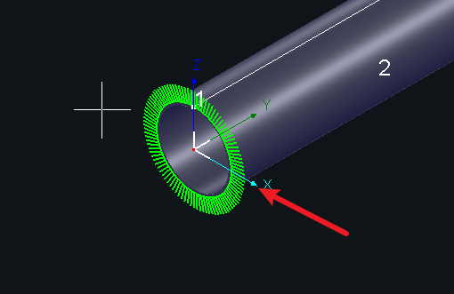
- Rough judgment: Check if the toolpath has a fringe line. A toolpath without a fringe is definitely not a bevel toolpath.

-
- Display judgment: Use 【Display→Show Normal Vectors】 to clearly observe if the normal vector (i.e., the actual swing angle of the cutting head) has an angle. An angle indicates swinging during actual cutting.

-
- Precise judgment: Click 【Measure】, then click the toolpath; the a-axis angle at that point will be displayed in the log.

-
- Simulation judgment: Simulate to see if the cutting head swings (a-axis angle).

2.How to use Recognize Bevel on the main interface?

Recognize Bevel is used to remedy cases where Create Bevel was forgotten when drawing parts within the software.

It is not suitable for externally imported drawings, which may fail to recognize the bevel. To avoid ambiguity, this function was removed in version 7.1.61.
3.How to operate when a part drawing has no bevel but bevel cutting is required?
(1)After drawing the part in 【Draw Part】, click 【Create Bevel】.
TubesT version limit: Version 1.45 and higher supports drawing bevel parts in TubesT.
TubePro version limit: Use with TubePro version 7.1.21.170.0 or higher; otherwise, it will not work.
(2)Add bevel to imported drawings within the software
【Add Bevel 】(automatic tool, fixed rule)
【Overlay AB-Axis Normal Vectors】 (manual adjustment)

4.Why do different versions handle overswing angle bevels differently when recognizing external drawings/generating TubeDraw drawings?
Before version 1.61, the built-in overswing angle handling for recognizing bevel saddles required manual overswing angle handling for Scan Bevel.
After version 1.61, Scan Bevel has built-in over-swing angle handling, meaning Scan Bevel after version 1.61 will not have overswing angles (using maximum cutting, i.e., material removal).
5.How to batch use Scan Bevel or Cancel Bevel?
To batch scan or cancel bevel for parts, select the parts in the part list and click Scan Bevel or Cancel Bevel.
Ⅰ. Overview
When processing parts that require bevel cutting (with the A-axis swinging during machining), and the drawing already shows the bevel shape, the bevel must be recognized during import.
Notice:
-
-
- If the actual machine tool is not a bevel machine, do not recognize the bevel, as it will make machining impossible.
- If the drawing does not show the bevel to be machined, it can be used 【Add Bevel】.
-
-
-
- The content in blue are clickable tutorial links. Click the link to view detailed parameter descriptions and usage methods for the corresponding functions.
-
Ⅱ. Function Description
1.Enable Bevel
Before using this function, click the small gear icon in the upper-left corner of the software, go to 【User Settings→Machine Config】, and check 【Bevel Cutting Head】.
A-axis swing angle limit: Recommended 45°. The maximum swing angle of the a-axis on the machine tool is ±45°. If different, confirm with the equipment manufacturer and enter the actual value.
A-axis swing length: Measures the swing length on the machine tool and enter the actual/approximate value. This value is only for correct display during simulation and does not affect actual nesting or processing.
2.Check Bevel during Import
Recognize Bevel: For part drawings created in external software, the bevel needs to be recognized first. In the parameter settings of Import from File , check Bevel. The bevel toolpath of the imported part will then match the bevel in the drawing.
Version impact:
-
-
-
- After version 7.1.61 (i.e. 2025v1), bevel can be recognized for all formats except *.sat. Files in *.step format are recommended.
- Before version 7.1.59, files in *.igs format are recommended.
-
-
3.Automatic Normal Vector Detection after Import
★ If a prompt appears after import which is about to perform Normal Vector Error Check, click OK.
If no prompt appears, you may configure based on the tutorial Normal Vector Error Check.
This will check the bevel toolpath of the imported files. And the error will be marked with a yellow triangle if there is an exception.
4. If Normal Vector Detection Finds Errors
The software will display a "small triangle exclamation mark" to locate: ① the part in the part list; ② the specific toolpath with the issue.
Hover the mouse over the "small triangle exclamation mark" to see the specific cause of the toolpath vector error.
If prompted "Part toolpath has overswing angle": Use 【Overswing Angle Handling】 to process the part.
If prompted Abnormal toolpath normal vector exists and the part is a closed section (such as square tubes or round tubes), check the prompted part in the part list, click 【Cancel Bevel】, then click 【Scan Bevel】 to batch re-recognize the bevel.
Supplementary notice on the Scan Bevel function: Scan Bevel is another method to recognize bevels, achieving the same result—recognizing the bevel angle. It differs only in the underlying method, so use it to re-recognize when issues occur.
Usage: Select the toolpath or part and click 【Scan Bevel】.
5. If errors persist and Scan Bevel cannot resolve them, or the part is an open section
① Turn on <Display Normal Vectors> to view the toolpath with the "small triangle exclamation mark" and check where the vector is incorrect.
② After locating the abnormal vector, verify if the drawing at this position is correctly drawn.
③ If the drawing is incorrect, modify it; if correct, ask the group owner in the technical communication group. (The community QR code is in About under the toolbar.)
Ⅲ. FAQs
1.How to determine if a part has been recognized with bevel?
-
- Simple judgment: The cross-section preview of the generated bevel part will have a bevel symbol.
-
- Rough judgment: Check if the toolpath has a fringe line. A toolpath without a fringe is definitely not a bevel toolpath.
-
- Display judgment: Use 【Display→Show Normal Vectors】 to clearly observe if the normal vector (i.e., the actual swing angle of the cutting head) has an angle. An angle indicates swinging during actual cutting.
-
- Precise judgment: Click 【Measure】, then click the toolpath; the a-axis angle at that point will be displayed in the log.
-
- Simulation judgment: Simulate to see if the cutting head swings (a-axis angle).
2.How to use Recognize Bevel on the main interface?
Recognize Bevel is used to remedy cases where Create Bevel was forgotten when drawing parts within the software.
It is not suitable for externally imported drawings, which may fail to recognize the bevel. To avoid ambiguity, this function was removed in version 7.1.61.
3.How to operate when a part drawing has no bevel but bevel cutting is required?
(1)After drawing the part in 【Draw Part】, click 【Create Bevel】.
TubesT version limit: Version 1.45 and higher supports drawing bevel parts in TubesT.
TubePro version limit: Use with TubePro version 7.1.21.170.0 or higher; otherwise, it will not work.
(2)Add bevel to imported drawings within the software
【Add Bevel 】(automatic tool, fixed rule)
【Overlay AB-Axis Normal Vectors】 (manual adjustment)
4.Why do different versions handle overswing angle bevels differently when recognizing external drawings/generating TubeDraw drawings?
Before version 1.61, the built-in overswing angle handling for recognizing bevel saddles required manual overswing angle handling for Scan Bevel.
After version 1.61, Scan Bevel has built-in over-swing angle handling, meaning Scan Bevel after version 1.61 will not have overswing angles (using maximum cutting, i.e., material removal).
5.How to batch use Scan Bevel or Cancel Bevel?
To batch scan or cancel bevel for parts, select the parts in the part list and click Scan Bevel or Cancel Bevel.

