

-
Products
Overview Products

-
2D Cutting
-
Tube Cutting
-
3D Cutting
-
Intelligent Welding
-
Intelligent Cutting Head
-
Industrial Automation
-
Industrial Software
-
Combination
-
Combination
BOCHU New Product -
Combination
BOCHU New Product -
Controller
BOCHU New Product -
2D Cutting Head
Tube Cutting Head
3D Cutting Head
Consumables
BOCHU New Product -
Servo
BOCHU New Product -
Industrial 4.0
-
- Support
- About
- Online Store


- Software Download
- Manual
- Video
- Tutorial
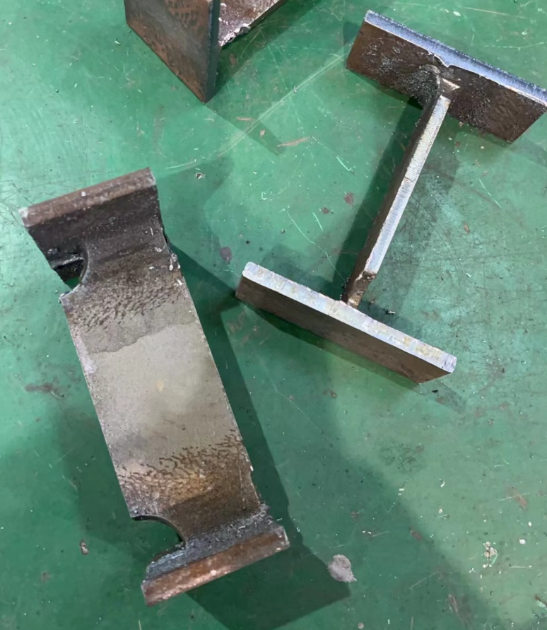
I. Overview
In the steel structure industry, common cutting features often appear during H-beam processing, such as V/Y bevels on the flange, bevels on the web, and weld scallop on the web.
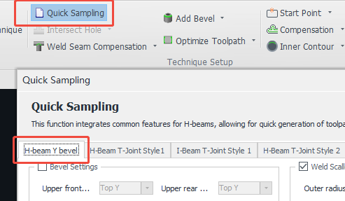
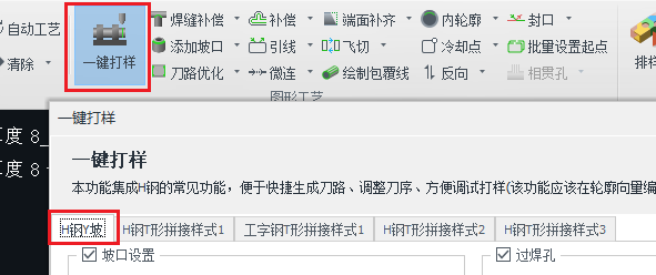
When there are no part drawings available during the trial run but you still want to test these standard cutting features, you can use the 【Quick Sampling: H-Beam Y Bevel】 to quickly generate toolpaths for standard parts—saving time on manual drawing and toolpath editing.
II. How to Use
1. Notes:
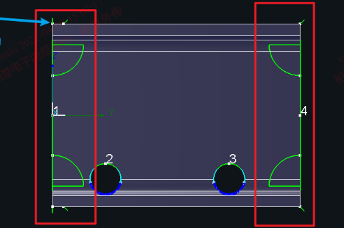
(1) Only supports H-beam parts where both ends are straight cuts (not tilt cuts) and do not contain any additional features. If you need round holes on the web, draw them in advance but do not modify the end faces.
(2) Always perform 【Collision-Avoid】 before 【Quick Sampling】.
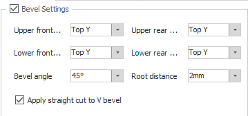
2. Flange Bevel:
-
- Each of the four flanges can be configured with a different bevel type. If set to Y bevel, you must enter a root face value.
-
- Apply straight cut to V bevel:
-
If the bevel cut alone can fully separate the Top V bevel during production, this option can remain unchecked.
-
If the cut is insufficient, enable this option. The system will add an additional straight cut at the V bevel to ensure complete separation. This reduces technique complexity.
-
- Apply straight cut to V bevel:

-
-
- If you prefer not to add an extra cut due to efficiency concerns, you can use the【Technique Assign】 -Hard Burn Off to fine-tune the technique for separation.
-
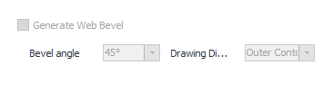
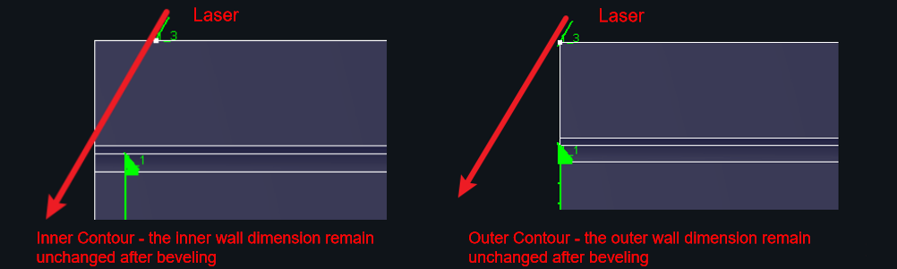
3. Web Bevel:
-
-
Drawing Dimensions:Affect the actual part size. See diagram below for reference.
-
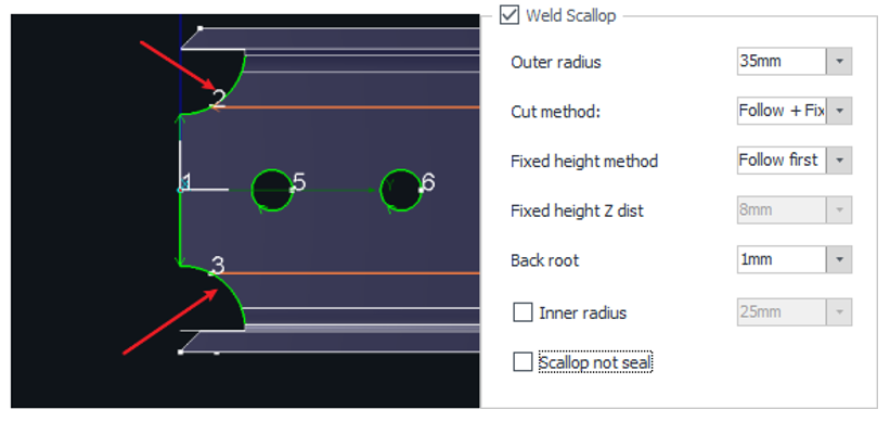
4. Weld Scallop:
-
- Outer Radius: Adjust the size of the weld scallop.
-
-
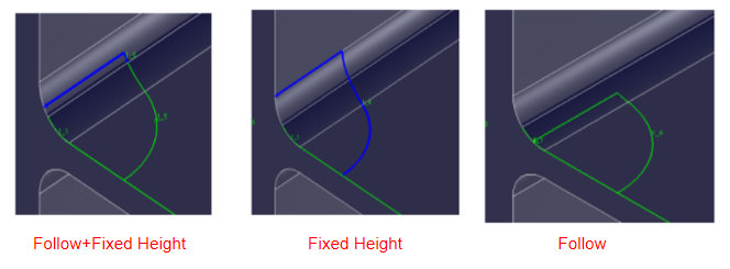
Cut Method:
-
Follow(recommended)
-
Supports bevels up to 45° of the R Corner, as the diagram show below.
-
Refer to 【H-beam Toolpath Angle】 for more details.
-
- Fixed Height
- Allows the toolpath to get as close as possible to the flange, achieving a minimal root.
- Since the kerf is wider, it’s recommended to use【Kerf Compensation(fixed height)】in combination.
- To use this mode, enable Fixed Height Cut and set a height value in the cutting software (i.e., TubePro or FACut-H).
- The nozzle should be higher than the flange during cutting.
-
-
-
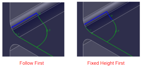
- Fixed Height Method (New in V1.51.3):
-
-
-
Only available when Cut Method is set to Follow + Fixed Height. This strategy adjusts the split point between the two toolpaths.
-
Follow First: The red arrow indicates the toolpath section calculated based on the maximum follow range from the Back Root. Although it may appear to damage the flange, the technique can be adjusted to avoid this.
-
Fixed Height First: The yellow arrow represents a toolpath that avoids intersecting with the inside edge of the flange, maintaining a minimum 2 mm distance—easier to control.
-
-

-
-
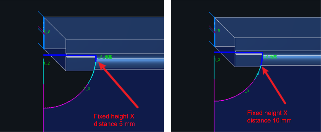
- Fxied Height Z Dist: Manually sets the toolpath split point.
-
-
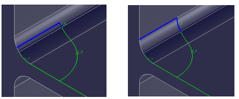
- Back Root: Adjusts the weld scallop position. Based on your expected root, the system will calculate the ideal toolpath location at the R Corner.
See diagram showing results of setting the root face from 2 mm to 0 mm.
-
- Inner Radius: When cutting bottom V/Y bevels, the scallop must be cut before the bevel to allow slag removal. Since the bevel cut may use high power and risk damaging the part, you can pre-cut a smaller hole. This hole absorbs the burn damage and will be removed with the bevel cut, protecting the final contour.

-
- If you prefer not to add extra cuts due to efficiency concerns, you can use the 【Technique Assign】- Anti-Burn to fine-tune the technique for separation—note that this requires higher technique control.
-
-
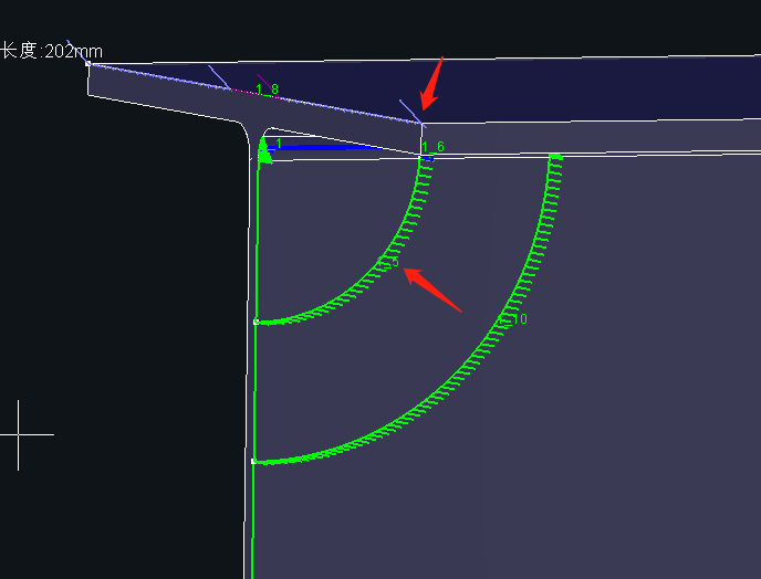
Scallop not Seal (New in V1.61.1):
-
To simplify unloading, you can seal the hole (see Diagram 1).
-
To improve cutting efficiency, you can leave it open (see Diagram 2).
-
-

I. Overview
In the steel structure industry, common cutting features often appear during H-beam processing, such as V/Y bevels on the flange, bevels on the web, and weld scallop on the web.
When there are no part drawings available during the trial run but you still want to test these standard cutting features, you can use the 【Quick Sampling: H-Beam Y Bevel】 to quickly generate toolpaths for standard parts—saving time on manual drawing and toolpath editing.
II. How to Use
1. Notes:
(1) Only supports H-beam parts where both ends are straight cuts (not tilt cuts) and do not contain any additional features. If you need round holes on the web, draw them in advance but do not modify the end faces.
(2) Always perform 【Collision-Avoid】 before 【Quick Sampling】.
2. Flange Bevel:
-
- Each of the four flanges can be configured with a different bevel type. If set to Y bevel, you must enter a root face value.
-
- Apply straight cut to V bevel:
-
If the bevel cut alone can fully separate the Top V bevel during production, this option can remain unchecked.
-
If the cut is insufficient, enable this option. The system will add an additional straight cut at the V bevel to ensure complete separation. This reduces technique complexity.
-
- Apply straight cut to V bevel:
-
-
- If you prefer not to add an extra cut due to efficiency concerns, you can use the【Technique Assign】 -Hard Burn Off to fine-tune the technique for separation.
-
3. Web Bevel:
-
-
Drawing Dimensions:Affect the actual part size. See diagram below for reference.
-
4. Weld Scallop:
-
- Outer Radius: Adjust the size of the weld scallop.
-
-
Cut Method:
-
Follow(recommended)
-
Supports bevels up to 45° of the R Corner, as the diagram show below.
-
Refer to 【H-beam Toolpath Angle】 for more details.
-
- Fixed Height
- Allows the toolpath to get as close as possible to the flange, achieving a minimal root.
- Since the kerf is wider, it’s recommended to use【Kerf Compensation(fixed height)】in combination.
- To use this mode, enable Fixed Height Cut and set a height value in the cutting software (i.e., TubePro or FACut-H).
- The nozzle should be higher than the flange during cutting.
-
-
-
- Fixed Height Method (New in V1.51.3):
-
-
-
Only available when Cut Method is set to Follow + Fixed Height. This strategy adjusts the split point between the two toolpaths.
-
Follow First: The red arrow indicates the toolpath section calculated based on the maximum follow range from the Back Root. Although it may appear to damage the flange, the technique can be adjusted to avoid this.
-
Fixed Height First: The yellow arrow represents a toolpath that avoids intersecting with the inside edge of the flange, maintaining a minimum 2 mm distance—easier to control.
-
-
-
-
- Fxied Height Z Dist: Manually sets the toolpath split point.
-
-
- Back Root: Adjusts the weld scallop position. Based on your expected root, the system will calculate the ideal toolpath location at the R Corner.
See diagram showing results of setting the root face from 2 mm to 0 mm.
-
- Inner Radius: When cutting bottom V/Y bevels, the scallop must be cut before the bevel to allow slag removal. Since the bevel cut may use high power and risk damaging the part, you can pre-cut a smaller hole. This hole absorbs the burn damage and will be removed with the bevel cut, protecting the final contour.
-
- If you prefer not to add extra cuts due to efficiency concerns, you can use the 【Technique Assign】- Anti-Burn to fine-tune the technique for separation—note that this requires higher technique control.
-
-
Scallop not Seal (New in V1.61.1):
-
To simplify unloading, you can seal the hole (see Diagram 1).
-
To improve cutting efficiency, you can leave it open (see Diagram 2).
-
-

