-
Products
Overview Products
-
2D Cutting
-
Tube Cutting
-
3D Cutting
-
Intelligent Welding
-
Intelligent Cutting Head
-
Industrial Automation
-
Industrial Software
-
Combination
-
Combination
BOCHU New Product -
Combination
BOCHU New Product -
Controller
BOCHU New Product -
2D Cutting Head
Tube Cutting Head
3D Cutting Head
Consumables
BOCHU New Product -
Servo
BOCHU New Product -
Industrial 4.0
-
- Support
- About
- Online Store


- Software Download
- Manual
- Video
- Tutorial
Ⅰ. Overview
During H-beam cutting, the cutting head can swing to form a bevel, but due to mechanical structure limitations, the maximum swing angle of the cutting head is typically ±45°. An alarm will trigger if this limit is exceeded.
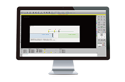
For efficient machining, when processing drawings in nesting, if the detected bevel angle exceeds ±45°, a pop-up prompt will appear during simulation and export.
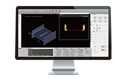
Meanwhile, the software will display a corresponding "overswing angle" prompt, which can be located: ① in the part list; ② the specific toolpath with the issue.
When the bevel angle of an externally imported part exceeds the maximum angle that the actual machine tool can process, such a drawing cannot be processed. To continue machining, use the 【Overswing Angle Handling】 function to adjust the drawing's bevel angle for processing.
Note: The content in blue are clickable tutorial links. Click the link to view detailed parameter descriptions and usage methods for the corresponding functions.
Ⅱ. Function Description
Starting from version 7.1.55, TubesT supports Overswing Angle Handling.
Starting from version 7.1.59, TubesT supports Overswing Angle Part Positioning.
If the function is missing, click the right link to upgrade the nesting software → Download link.
Click【Add Bevel】 at the top of the software → select 【Overswing Angle Handling】 from the drop-down menu.
Maximum Outline: Adds more cutting points to ensure that after adjusting the angle of over-swing toolpaths, part splicing does not interfere.
Minimum Outline: Reduces cutting points to ensure that after adjusting the angle, the part body has no missing material. Excess material can be ground later to match the original drawing.
The effective range can be selected as needed by checking <Current view> or <Part List>.
★Note: For I-beam toolpaths, overswing handling may cause toolpath disconnection (see images in FAQs below). It is recommended to modify the flange angle directly in Optimize Toolpath.
★ Note: For other unclosed sections (e.g., angle steel, channel steel), inspect the part toolpaths as detailed below.
3.Operating Videos
Ⅲ. FAQs
Why does the simulation still show 50° or the machine prompts overswing after the software's over-swing detection passes?
Check if the cutting head swing angle setting (below) is 45°. If not, reset it to the default 45°.
When set to 60°, over-swing handling only processes toolpaths exceeding 60°. A 50° bevel angle will not be processed.
2.How to determine the specific angle of the current overswing toolpath?
(1)Select a toolpath and click Simulate; the real-time swing angle will display in the lower-right corner.
(2)Click Measure, then click a toolpath; the swing angle will show in the log.
3.After Over-Swing Angle Handling, open sections like angle steel, channel steel, or I-beams have disconnected toolpaths. What should I do?
Currently, disconnection issues only occur in unclosed sections.
For I-beams: Use Optimize Toolpath to adjust flange angles, or increase power to burn through.
For other profiles: Check for part damage, use LC Pattern to avoid damage, or adjust processes to burn through.
If none of the above works, modify the original drawing or filter out parts with bevels exceeding 45° to skip machining.
As shown below, after adjustment, one side of the flange may disconnect from the web, and the other side may be over-cut. Pay attention to process debugging afterward.


