

-
Products
Overview Products

-
2D Cutting
-
Tube Cutting
-
3D Cutting
-
Intelligent Welding
-
Intelligent Cutting Head
-
Industrial Automation
-
Industrial Software
-
Combination
-
Combination
BOCHU New Product -
Combination
BOCHU New Product -
Controller
BOCHU New Product -
2D Cutting Head
Tube Cutting Head
3D Cutting Head
Consumables
BOCHU New Product -
Servo
BOCHU New Product -
Industrial 4.0
-
- Support
- About
- Online Store


- Software Download
- Manual
- Video
- Tutorial
Ⅰ. Overview
The Microjoint function is used to secure parts and prevent them from falling during cutting. When microjoints are required, they can be added either manually or in batches.
Typical application scenarios include, but are not limited to:

Note: Blue text indicates clickable tutorial links. You can click a link to view detailed descriptions and instructions for the corresponding feature.
Ⅱ. How to use
1. Manual Set Microjoint:
Click Microjoint, set the size, and then click any position on the graphic trajectory to add a microjoint.
You can choose whether to Change start point to microjoint or Add lead at microjoint.

The parameters are explained as follows:
① Root ratio: If a smooth microjoint is required, refer to the tutorial to configure the value.
② Change start point to microjoint: The effect of enabling or disabling this option is shown in the illustration below.

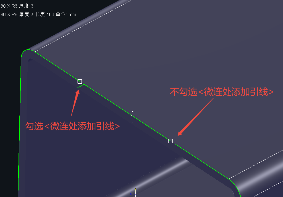
③Add lead at microjoint: The effect of enabling or disabling this option is shown in the illustration below.
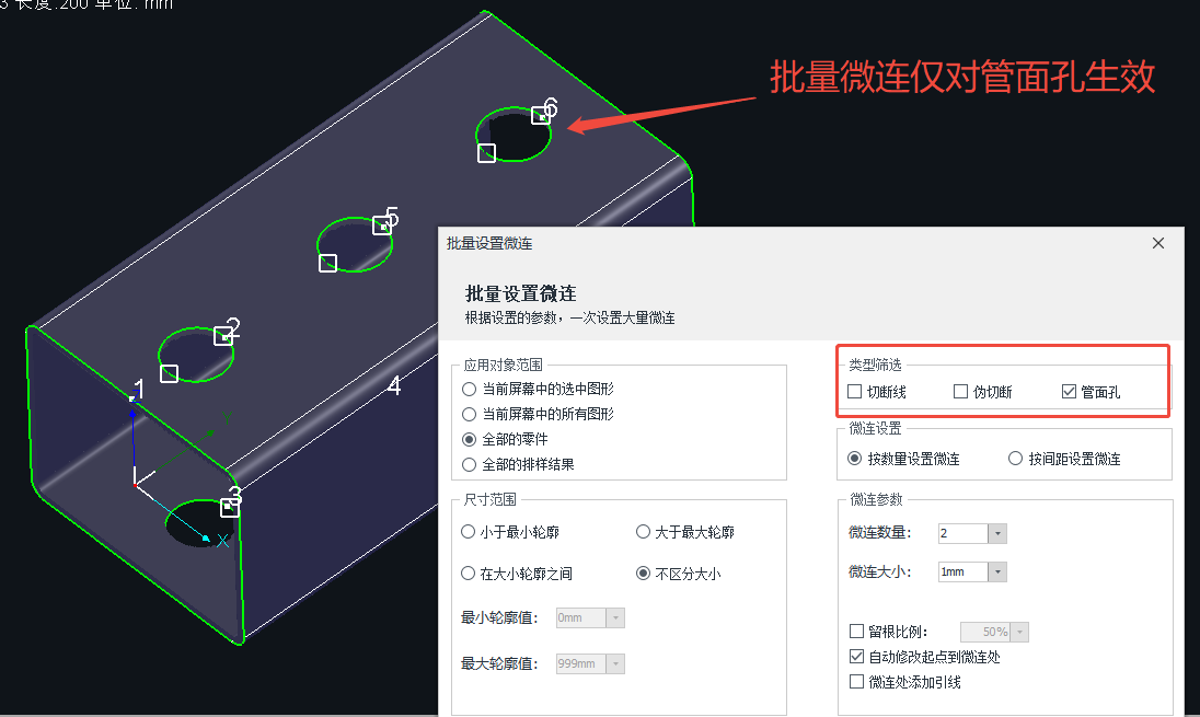
2. Batch Set Microjoint
To add microjoints in batches to imported parts, click Batch Set Microjoint from the Microjoint drop-down menu.

The parameters are explained as follows:
① Microjoint Settings: You can choose to set microjoints by number or by interval.

② Microjoint Params: You can configure the microjoint Number/Interval or Size, and whether to enable Root ratio, Change start point to microjoint, or Add lead at microjoint.
The Avoid Microjoint option has been added starting from TubesT 2025 V3.
This option allows you to define avoid distances and vertex angles so that microjoints are not placed at corners or vertices, reducing issues such as difficult piercing at corners and unstable cutting processes.
-
-
-
-
Avoid distance: Microjoints will be added at positions offset by a specified distance before and after corners or vertices.
-
Max vertex angle: Sets the maximum vertex angle within which microjoints will not be added.
-
-
-
♣ Notes:
① Corner avoidance is only effective for rectangular tubes and square tubes.
② The range of Max vertex angle is 0~180°. When set to 180°, straight segments may also be identified as vertices. Please configure this parameter carefully.


※ From 25 V3, avoiding corners and vertices for microjoints is supported
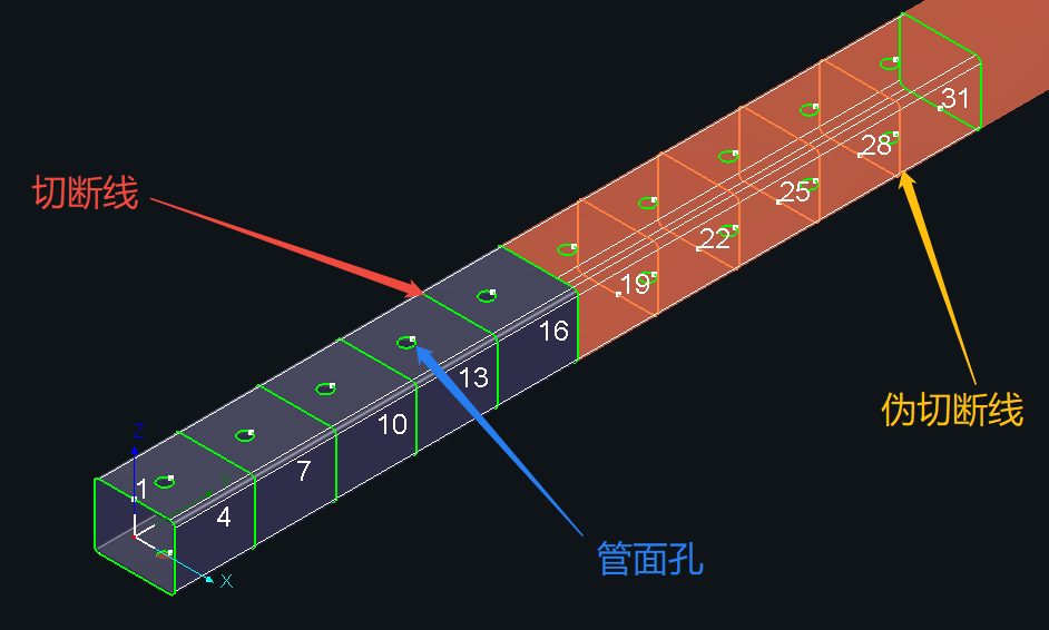
③ Select: Includes Cutoff line, Pseudo cutoff (after Merge parts, intermediate cutoff toolpaths of merged parts become pseudo cutoffs), and Tube holes.
Note: If microjoints are not added to certain graphics, check whether the application scope, size range, and type filter settings are appropriate.
④ Size Range: Used when microjoints are required only for toolpaths within a specific length range.
You can choose Under min size, Over max size, In between and Apply to all.
If there are no special requirements, just select Apply to all.
⑤ Apply to: Select the objects to which the settings apply. For details, refer to TubesT - How to choose the scope of application?
3. Auto Microjoint
After enabling Enable Auto Microjoint under Auto Technique, microjoints will be automatically added to subsequently imported parts.
The parameters are similar to those in Batch Set Microjoint.

4、Clear Microjoint
Select the graphics from which microjoints need to be removed, then click Clear Microjoint or Clear Smooth Microjoint from the Clear drop-down menu.

Ⅲ. FAQs
1. Why does the toolpath of single-line marked text become abnormal after clearing microjoints?
Single-line text is implemented with hidden microjoints at the underlying level to achieve a segmented character appearance. After microjoints are cleared, as a result, the toolpath becomes a single continuous original curve.
Starting from TubesT 25 V3, the Clear Microjoint function no longer applies to text added using the Marking feature under Add Text. If this issue occurs, upgrade the software to 25 V3 or later.
2. Why are microjoints unevenly distributed on the four sides?
To achieve evenly distributed microjoints when adding them in batches, proper configuration of Microjoint parameters is required.
You can try adjusting the microjoint interval, enabling Change start point to microjoint, or manually adding microjoints.
For example, when adding four microjoints to a square tube cutoff line, enabling Change start point to microjoint can achieve even distribution.
The illustration below shows the difference before and after enabling this option.


3. Can FlyCut still be used when Microjoint is applied??
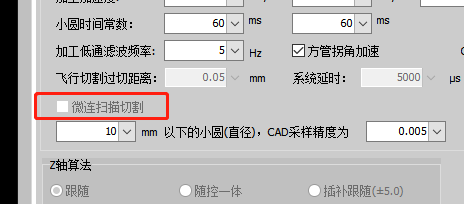
When microjoints are applied in TubesT, FlyCut is not enabled by default. If you want to process microjoint toolpaths with FlyCut, you must enable MicroJoint to scan under Global Parameter → MotionParameters in TubePro.
This function is supported in TubePro 145.2 and later.
Note: The MicroJoint to scan function is subject to machine model limitations. Please contact the manufacturer’s after-sales service for availability.
Ⅰ. Overview
The Microjoint function is used to secure parts and prevent them from falling during cutting. When microjoints are required, they can be added either manually or in batches.
Typical application scenarios include, but are not limited to:
Note: Blue text indicates clickable tutorial links. You can click a link to view detailed descriptions and instructions for the corresponding feature.
Ⅱ. How to use
1. Manual Set Microjoint:
Click Microjoint, set the size, and then click any position on the graphic trajectory to add a microjoint.
You can choose whether to Change start point to microjoint or Add lead at microjoint.
The parameters are explained as follows:
① Root ratio: If a smooth microjoint is required, refer to the tutorial to configure the value.
② Change start point to microjoint: The effect of enabling or disabling this option is shown in the illustration below.
③Add lead at microjoint: The effect of enabling or disabling this option is shown in the illustration below.
2. Batch Set Microjoint
To add microjoints in batches to imported parts, click Batch Set Microjoint from the Microjoint drop-down menu.
The parameters are explained as follows:
① Microjoint Settings: You can choose to set microjoints by number or by interval.
② Microjoint Params: You can configure the microjoint Number/Interval or Size, and whether to enable Root ratio, Change start point to microjoint, or Add lead at microjoint.
The Avoid Microjoint option has been added starting from TubesT 2025 V3.
This option allows you to define avoid distances and vertex angles so that microjoints are not placed at corners or vertices, reducing issues such as difficult piercing at corners and unstable cutting processes.
-
-
-
-
Avoid distance: Microjoints will be added at positions offset by a specified distance before and after corners or vertices.
-
Max vertex angle: Sets the maximum vertex angle within which microjoints will not be added.
-
-
-
♣ Notes:
① Corner avoidance is only effective for rectangular tubes and square tubes.
② The range of Max vertex angle is 0~180°. When set to 180°, straight segments may also be identified as vertices. Please configure this parameter carefully.
※ From 25 V3, avoiding corners and vertices for microjoints is supported
③ Select: Includes Cutoff line, Pseudo cutoff (after Merge parts, intermediate cutoff toolpaths of merged parts become pseudo cutoffs), and Tube holes.
Note: If microjoints are not added to certain graphics, check whether the application scope, size range, and type filter settings are appropriate.
④ Size Range: Used when microjoints are required only for toolpaths within a specific length range.
You can choose Under min size, Over max size, In between and Apply to all.
If there are no special requirements, just select Apply to all.
⑤ Apply to: Select the objects to which the settings apply. For details, refer to TubesT - How to choose the scope of application?
3. Auto Microjoint
After enabling Enable Auto Microjoint under Auto Technique, microjoints will be automatically added to subsequently imported parts.
The parameters are similar to those in Batch Set Microjoint.
4、Clear Microjoint
Select the graphics from which microjoints need to be removed, then click Clear Microjoint or Clear Smooth Microjoint from the Clear drop-down menu.
Ⅲ. FAQs
1. Why does the toolpath of single-line marked text become abnormal after clearing microjoints?
Single-line text is implemented with hidden microjoints at the underlying level to achieve a segmented character appearance. After microjoints are cleared, as a result, the toolpath becomes a single continuous original curve.
Starting from TubesT 25 V3, the Clear Microjoint function no longer applies to text added using the Marking feature under Add Text. If this issue occurs, upgrade the software to 25 V3 or later.
2. Why are microjoints unevenly distributed on the four sides?
To achieve evenly distributed microjoints when adding them in batches, proper configuration of Microjoint parameters is required.
You can try adjusting the microjoint interval, enabling Change start point to microjoint, or manually adding microjoints.
For example, when adding four microjoints to a square tube cutoff line, enabling Change start point to microjoint can achieve even distribution.
The illustration below shows the difference before and after enabling this option.
3. Can FlyCut still be used when Microjoint is applied??
When microjoints are applied in TubesT, FlyCut is not enabled by default. If you want to process microjoint toolpaths with FlyCut, you must enable MicroJoint to scan under Global Parameter → MotionParameters in TubePro.
This function is supported in TubePro 145.2 and later.
Note: The MicroJoint to scan function is subject to machine model limitations. Please contact the manufacturer’s after-sales service for availability.

