

-
Products
Overview Products

-
2D Cutting
-
Tube Cutting
-
3D Cutting
-
Intelligent Welding
-
Intelligent Cutting Head
-
Industrial Automation
-
Industrial Software
-
Combination
-
Combination
BOCHU New Product -
Combination
BOCHU New Product -
Controller
BOCHU New Product -
2D Cutting Head
Tube Cutting Head
3D Cutting Head
Consumables
BOCHU New Product -
Servo
BOCHU New Product -
Industrial 4.0
-
- Support
- About
- Online Store


- Software Download
- Manual
- Video
- Tutorial
I. Introduction
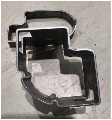
I-beams and profiled pipes with concave angles may cause collisions when processed directly without any treatment, especially when machining reaches the concave angles. In such cases, the contour vector needs to be modified.
Cutting head strikes pipe wall
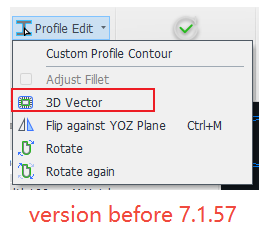
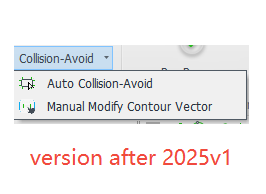
Starting from version 7.1.57, the original "3D Vector" in Profile Edit function has been upgraded to "Collision-Avoid" (i.e. Vector Modify), and the cutting head model has also been upgraded from a 2D model in the chc format to a 3D model in the ses format.
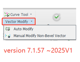
For toolpath anti-collision detection, it is recommended to prioritize the use of the Auto Modify function. For details on how to use it and the specific differences between ses and chc, refer to the "Vector Modify" section.
If the Auto Modify fails or does not produce the desired result, manual adjustments can also be made.
Note: In manual modifications, the boundaries remain consistent with Auto Modify.
The 3D cutting head in the ses format can detect bevel toolpaths (though the flange of H-beams is not currently detected). The 2D cutting head in the chc format cannot detect bevel toolpaths and can only detect contour vectors.
II. How to Use
1.Permissions Related:
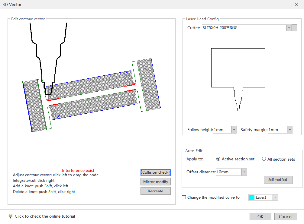
Before version 7.1.57, manual editing of the contour vector was performed in the "3D Vector" function.
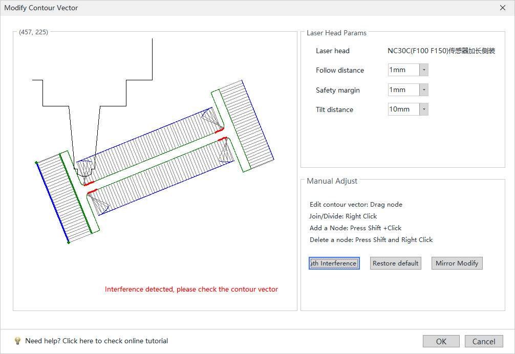
Starting from version 7.1.57, manual editing of the contour vector is done in "Auto Collision-Avoid" → "Manual Modify Contour Vector" (i.e. "Manual Modify Non-Bleve Vector").

2. Operation Steps:
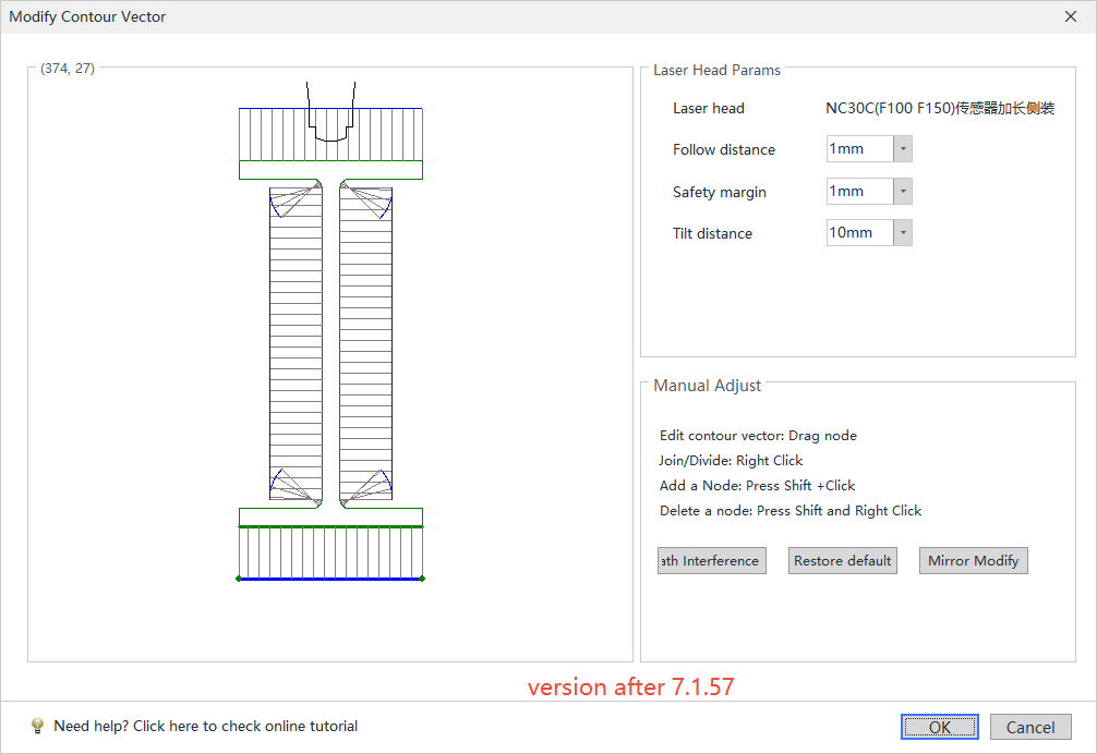
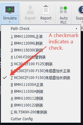
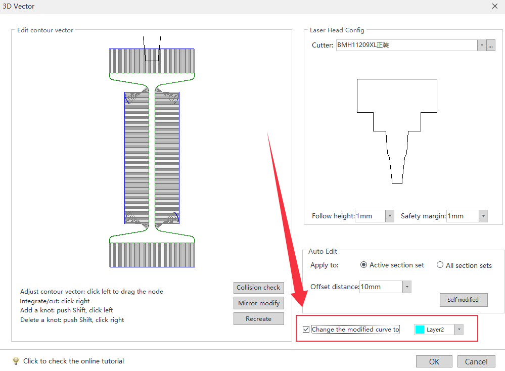
Select the cutting head model actually used for machining on the machine tool. Note: Do not randomly select a model.
Click "collision check." The software will indicate potential collisions and highlight the interfering areas in red.
Modify one chamfer first:
Hold Shift and left-click to add nodes in non-interfering areas to avoid accidental dragging.
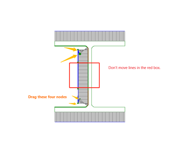
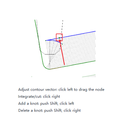
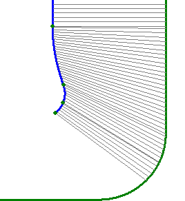
Hold the left mouse button and drag the nodes in the interfering section until no collision remains. The red highlight on that chamfer will disappear.
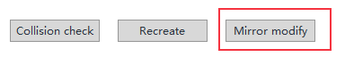
For I-beams:
Click "Mirror Modify" to automatically adjust the other three chamfers in one step.
For Profiled Pipes:
In versions prior to 7.1.57.1, it is recommended to check the option "Change the modified curve to"
Since the cutting direction is modified, the actual cutting thickness often increases. Automatically placing this part of the toolpath on a separate process layer allows for assigning a different cutting process in TubePro during machining.
After editing, click "Check Toolpath" again. Once the check passes, proceed with simulation. Only after confirming no errors should you export for machining.
Ⅲ. FAQS
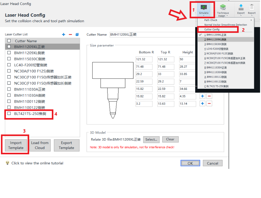
- How to import a newly configured ses model?
- What is the meaning of each parameter in 【Auto Modify】?
Follow height: The height of the cutting head to the upper surface of the part entity. Usually set to 1mm without changing.
Safety margin: The 1mm Safety margin rule applies differently per model.
① Chc format: Expands both sides of the model by 1mm for collision avoidance.
② Ses format: Maintains ≥1mm gap between cutting head (excluding nozzle) and part geometry.
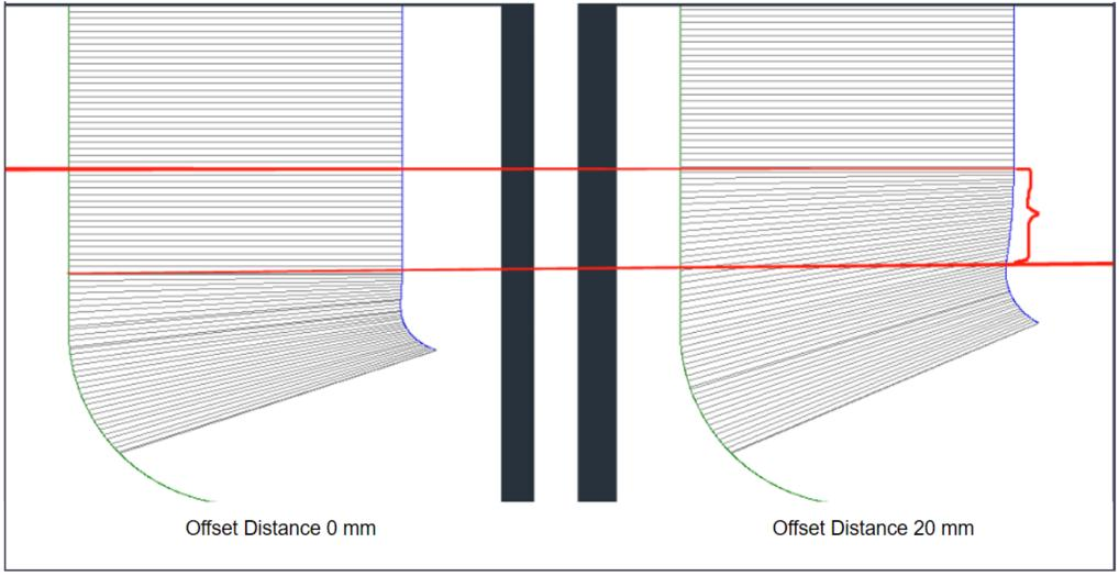
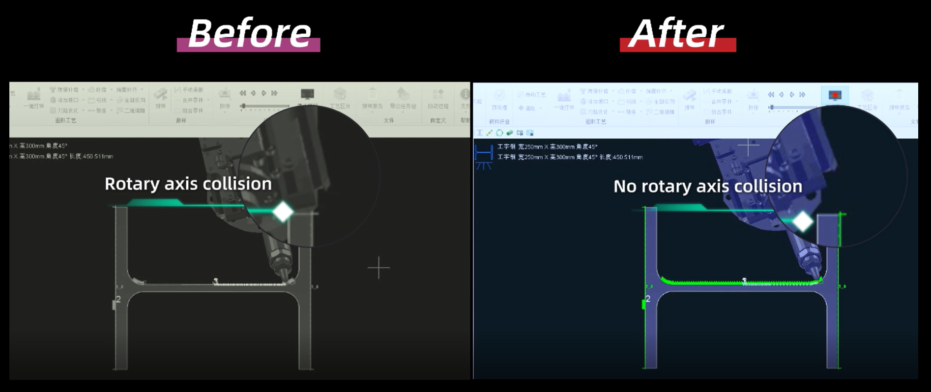
Offset distance(Tilt/Swing distance): When the I-beam wing plate is deformed, the actual processing may have the risk of collision, at this time, you can adjust the <Offset Distance>, so that the cutting head near the R corner according to the set swing distance ahead of the swing.
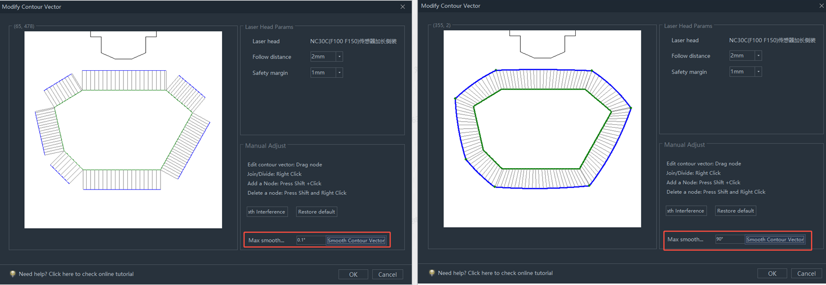
Smooth Maximum Angle: When the profiled pipe knife path has a sudden change in normal vector at the corner, the transition can be made by smoothing the maximum angle.
I. Introduction
I-beams and profiled pipes with concave angles may cause collisions when processed directly without any treatment, especially when machining reaches the concave angles. In such cases, the contour vector needs to be modified.
Cutting head strikes pipe wall
Starting from version 7.1.57, the original "3D Vector" in Profile Edit function has been upgraded to "Collision-Avoid" (i.e. Vector Modify), and the cutting head model has also been upgraded from a 2D model in the chc format to a 3D model in the ses format.
For toolpath anti-collision detection, it is recommended to prioritize the use of the Auto Modify function. For details on how to use it and the specific differences between ses and chc, refer to the "Vector Modify" section.
If the Auto Modify fails or does not produce the desired result, manual adjustments can also be made.
Note: In manual modifications, the boundaries remain consistent with Auto Modify.
The 3D cutting head in the ses format can detect bevel toolpaths (though the flange of H-beams is not currently detected). The 2D cutting head in the chc format cannot detect bevel toolpaths and can only detect contour vectors.
II. How to Use
1.Permissions Related:
Before version 7.1.57, manual editing of the contour vector was performed in the "3D Vector" function.
Starting from version 7.1.57, manual editing of the contour vector is done in "Auto Collision-Avoid" → "Manual Modify Contour Vector" (i.e. "Manual Modify Non-Bleve Vector").
2. Operation Steps:
Select the cutting head model actually used for machining on the machine tool. Note: Do not randomly select a model.
Click "collision check." The software will indicate potential collisions and highlight the interfering areas in red.
Modify one chamfer first:
Hold Shift and left-click to add nodes in non-interfering areas to avoid accidental dragging.
Hold the left mouse button and drag the nodes in the interfering section until no collision remains. The red highlight on that chamfer will disappear.
For I-beams:
Click "Mirror Modify" to automatically adjust the other three chamfers in one step.
For Profiled Pipes:
In versions prior to 7.1.57.1, it is recommended to check the option "Change the modified curve to"
Since the cutting direction is modified, the actual cutting thickness often increases. Automatically placing this part of the toolpath on a separate process layer allows for assigning a different cutting process in TubePro during machining.
After editing, click "Check Toolpath" again. Once the check passes, proceed with simulation. Only after confirming no errors should you export for machining.
Ⅲ. FAQS
- How to import a newly configured ses model?
- What is the meaning of each parameter in 【Auto Modify】?
Follow height: The height of the cutting head to the upper surface of the part entity. Usually set to 1mm without changing.
Safety margin: The 1mm Safety margin rule applies differently per model.
① Chc format: Expands both sides of the model by 1mm for collision avoidance.
② Ses format: Maintains ≥1mm gap between cutting head (excluding nozzle) and part geometry.
Offset distance(Tilt/Swing distance): When the I-beam wing plate is deformed, the actual processing may have the risk of collision, at this time, you can adjust the <Offset Distance>, so that the cutting head near the R corner according to the set swing distance ahead of the swing.
Smooth Maximum Angle: When the profiled pipe knife path has a sudden change in normal vector at the corner, the transition can be made by smoothing the maximum angle.

