

-
Products
Overview Products

-
2D Cutting
-
Tube Cutting
-
3D Cutting
-
Intelligent Welding
-
Intelligent Cutting Head
-
Industrial Automation
-
Industrial Software
-
Combination
-
Combination
BOCHU New Product -
Combination
BOCHU New Product -
Controller
BOCHU New Product -
2D Cutting Head
Tube Cutting Head
3D Cutting Head
Consumables
BOCHU New Product -
Servo
BOCHU New Product -
Industrial 4.0
-
- Support
- About
- Online Store


- Software Download
- Manual
- Video
- Tutorial
I. Introduction
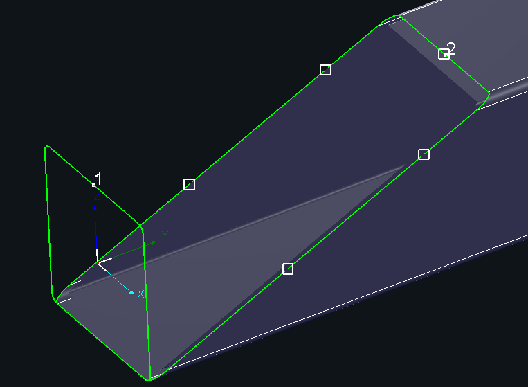
For parts with a large inclination angle on the left or right end, or with an incomplete section due to gap on the end face, after machining the end-face cut-off line, the part needs to be re-clamped for reverse cutting.
However, if the end-face gap is too large, the chuck may fail to clamp the part securely, and the part may even slip into the middle chuck.
Therefore, the Make Up Tilt End function is provided to fill the gap on the end-face cut-off line and allow automatic microjoints to be added, making it easier for the jaws to clamp the part.
Notice: Bold texts in blue are tutorial links. Click the links to view detailed parameter descriptions and instructions for the corresponding function.
II. How to Use
1. Function Location

Notice: In the Steel Section Edition, this function is available in the technique setup interface in the top function bar.

2. Mode

(1) Custom setup (also known as Standard Make Up Tilt End, introduced in version 7.1.41)


① General Parameters
Cutoff type: Choose between front or rear cut-off line depending on which side of the part needs completion.
Offset: The distance between the completed cut-off line and the original tilt cut-off line.

Length limit (above): When checked, parts longer than the set value can be added with the make up toolpath for tilt end, while shorter parts will not.
② Apply to
This function can be applied to Current view/Part list/Nest list, with options of Selected/All.
When applied to Nest list, it may affect co-edge conditions, possibly reducing material utilization.
③ Microjoint
Determine whether to add microjoints on tilt cut-off toolpaths. (A microjoint leaves a small uncut section on the toolpath to allow jaws to clamp the part during reverse cutting.)
After adding microjoints, check whether they are located at tube corners. If so, adjust the microjoint parameters and reprocess the part.
(2) Auto setup (introduced in version 7.1.47)

This mode is similar to custom setup and requires parameter settings as described above. However:
① There is no need to select Cutoff type in general parameter.
② There is no need to set microjoint parameters, as microjoints will be added automatically once Make Up Tilt End is completed.

In addition, auto setup can be applied intelligently in certain cases:
① For island strip holes on the web of an I-beam, when the ratio of Y-length to X-length ≥ 4, a microjoint is added automatically; if the ratio is less than 4, no microjoint is added.
② For edge islands, cross-face islands, tilt cuts, or Z-shaped island holes, when the Y-length ≥ jaw length, a microjoint is added automatically; if less, no microjoint is added.
Notice: Jaw length corresponds to parameter B3 grip length in User Settings → Machine Config.

(3) Clear
The Clear option allows you to clear make up toolpath for tilt end within a defined scope, enabling batch removal.
Notice: To clear make up toolpath for tilt end for a single part, select the part, then go to Clear → Clear Makeup Toolpath on Tilt End.

3. Other Use Cases: Center Z Shape of Loop Nesting
In the Auto Nest interface, when the Central Z Shape of Loop Nesting is enabled, you can select Make Up Tilt End and set the relevant parameters.
In this case, make up lines for tilt end are automatically added to the central Z shape in the nesting results.

The definitions of Cut-off type, Offset, and Microjoint are the same as described above.
Enable Gap Restrict:
When checked, if the gap length on the part end face is smaller than the jaw length, neither make up lines for tilt end nor microjoints will be added.
III. Operation Demo
IV. Notes
1. Why does the following popup appear?

The minimum unit for Make Up Tilt End is a part. When a toolpath is selected and the scope is set to Current view – Selected, the software attempts to apply the command directly to the toolpath, which triggers the popup message.
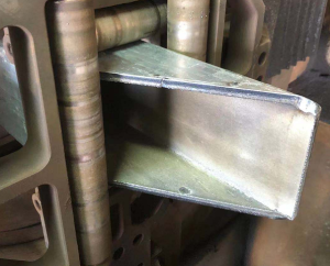
V. Actual Machining Effect
I. Introduction
For parts with a large inclination angle on the left or right end, or with an incomplete section due to gap on the end face, after machining the end-face cut-off line, the part needs to be re-clamped for reverse cutting.
However, if the end-face gap is too large, the chuck may fail to clamp the part securely, and the part may even slip into the middle chuck.
Therefore, the Make Up Tilt End function is provided to fill the gap on the end-face cut-off line and allow automatic microjoints to be added, making it easier for the jaws to clamp the part.
Notice: Bold texts in blue are tutorial links. Click the links to view detailed parameter descriptions and instructions for the corresponding function.
II. How to Use
1. Function Location
Notice: In the Steel Section Edition, this function is available in the technique setup interface in the top function bar.
2. Mode
(1) Custom setup (also known as Standard Make Up Tilt End, introduced in version 7.1.41)
① General Parameters
Cutoff type: Choose between front or rear cut-off line depending on which side of the part needs completion.
Offset: The distance between the completed cut-off line and the original tilt cut-off line.
Length limit (above): When checked, parts longer than the set value can be added with the make up toolpath for tilt end, while shorter parts will not.
② Apply to
This function can be applied to Current view/Part list/Nest list, with options of Selected/All.
When applied to Nest list, it may affect co-edge conditions, possibly reducing material utilization.
③ Microjoint
Determine whether to add microjoints on tilt cut-off toolpaths. (A microjoint leaves a small uncut section on the toolpath to allow jaws to clamp the part during reverse cutting.)
After adding microjoints, check whether they are located at tube corners. If so, adjust the microjoint parameters and reprocess the part.
(2) Auto setup (introduced in version 7.1.47)
This mode is similar to custom setup and requires parameter settings as described above. However:
① There is no need to select Cutoff type in general parameter.
② There is no need to set microjoint parameters, as microjoints will be added automatically once Make Up Tilt End is completed.
In addition, auto setup can be applied intelligently in certain cases:
① For island strip holes on the web of an I-beam, when the ratio of Y-length to X-length ≥ 4, a microjoint is added automatically; if the ratio is less than 4, no microjoint is added.
② For edge islands, cross-face islands, tilt cuts, or Z-shaped island holes, when the Y-length ≥ jaw length, a microjoint is added automatically; if less, no microjoint is added.
Notice: Jaw length corresponds to parameter B3 grip length in User Settings → Machine Config.
(3) Clear
The Clear option allows you to clear make up toolpath for tilt end within a defined scope, enabling batch removal.
Notice: To clear make up toolpath for tilt end for a single part, select the part, then go to Clear → Clear Makeup Toolpath on Tilt End.
3. Other Use Cases: Center Z Shape of Loop Nesting
In the Auto Nest interface, when the Central Z Shape of Loop Nesting is enabled, you can select Make Up Tilt End and set the relevant parameters.
In this case, make up lines for tilt end are automatically added to the central Z shape in the nesting results.
The definitions of Cut-off type, Offset, and Microjoint are the same as described above.
Enable Gap Restrict:
When checked, if the gap length on the part end face is smaller than the jaw length, neither make up lines for tilt end nor microjoints will be added.
III. Operation Demo
IV. Notes
1. Why does the following popup appear?
The minimum unit for Make Up Tilt End is a part. When a toolpath is selected and the scope is set to Current view – Selected, the software attempts to apply the command directly to the toolpath, which triggers the popup message.
V. Actual Machining Effect

