

-
Products
Overview Products

-
2D Cutting
-
Tube Cutting
-
3D Cutting
-
Intelligent Welding
-
Intelligent Cutting Head
-
Industrial Automation
-
Industrial Software
-
Combination
-
Combination
BOCHU New Product -
Combination
BOCHU New Product -
Controller
BOCHU New Product -
2D Cutting Head
Tube Cutting Head
3D Cutting Head
Consumables
BOCHU New Product -
Servo
BOCHU New Product -
Industrial 4.0
-
- Support
- About
- Online Store


- Software Download
- Manual
- Video
- Tutorial
I. Introduction
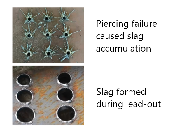
What should be done when poor cutting quality during piercing results in slag that affects the lead-in, or when slag forms due to deceleration and increased laser energy during lead-out? — Add a lead line.
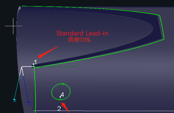
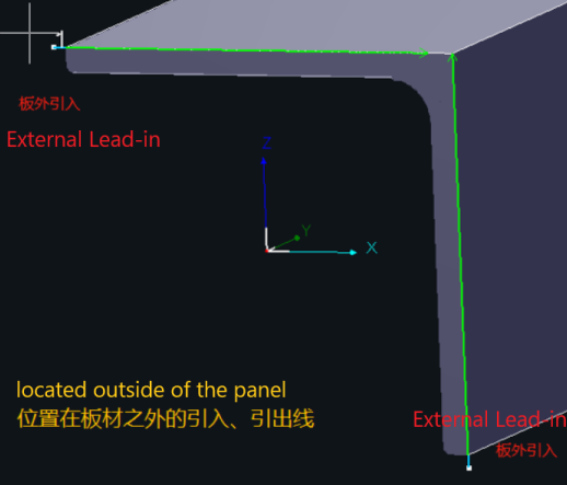
In TubesT, there are two types of lead-in lines: Standard Lead line and External Lead line.
| Standard Lead Line | External Lead Line | |
| Used for closed-section tubes and regular tube surface holes. | Used for sheet steel sections (such as angle steel, channel steel, I-beams) and flange holes. | |
| Lead-in |
Features & Cutting Process:
|
Features & Cutting Process:
|
| Lead-out |
Features & Cutting Process: Scenario (Standard Lead-out):
Note: Do not place a lead-out line on the left cutting path of a part to avoid cutting air (missing the intended cut). |
Features & Cutting Process: Scenario (External Lead-out):
|
Ⅱ. How to use
Note: <>, 【】 in the contents of the tutorial links can be jumped, click on the link, you can view the function corresponding to the detailed parameters of the description, the use of the method.
1. Automatically added
| Standard Lead Line | External Lead Line |
|
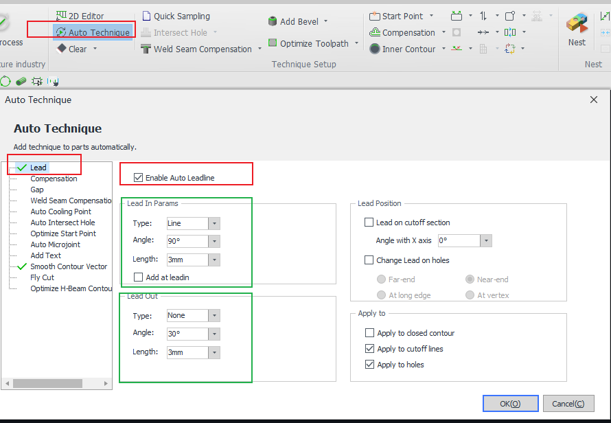
Before importing parts, turn on 【Lead】 in 【Auto Technique】.
|
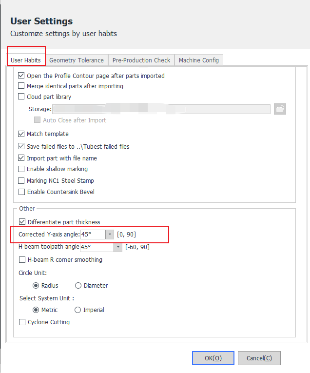
When importing parts, set the length of the off-board leads in 【Import Parameters】. Note: Once set here, the lead length of the part drawn in the software will be this value. Note: If the end face of your part is rounded, you can set the angle of the off-board lead in 【Corrected Y-axis angle】.
|

2. Add manually
| Standard Lead Line | External Lead Line |
|
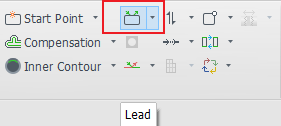
After importing the part, click [Lead] in the toolbar.
|
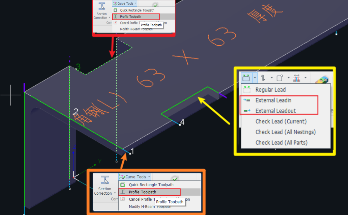
After importing the part, set the length of the off-board lead in 【Profile Toolpath】.
|
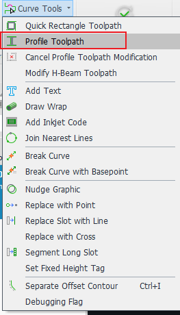
Note that when the toolpath is a Profile Toolpath, you have to use the method in the 【Profile Toolpath】tutorial to add off-board leads;
When you want to add an off-board lead to an ordinary flange hole (a flange hole without a notch, that is, a non-special toolpath), you can add an off-board lead directly in the drop-down button of the main interface 【Lead】, as shown in the following example.
How to determine whether it is a special toolpath? -Select the toolpath, see whether the toolbar 【Profile Toolpath】 button is lit up, lit up is a special toolpath, if grayed out is an ordinary toolpath.
3. Parameter interpretation.
Parameter |
Interpretation. |
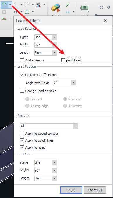
| Line Type |
There are three types available. The effect of using a Straight + Arc lead-in is shown in the figure below.
|
| Angle | The angle between the lead-in and the cutting path. |
| Length | The length of the lead-in. |
| Add at leadin(Lead-in Cooling Point) | Automatically adds a cooling point at the end of the lead-in. |
| Joint Lead |
Continuous Cutting
|
| Lead-out Line |
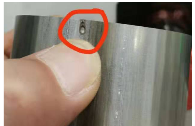
When processing tubes, due to gravity, the part may fall before the cutting path is complete. This can cause the laser to hit the part directly before finishing the cut, resulting in burn marks and affecting the part’s appearance. Setting a lead-out line helps prevent such thermal damage. |
| Lead on cutoff section |
Checked: Changes the start point on the cutting face while setting the lead-in. Unchecked: The lead-in is added to the original start point of the cutting line. |
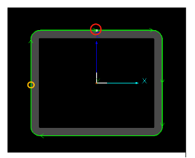
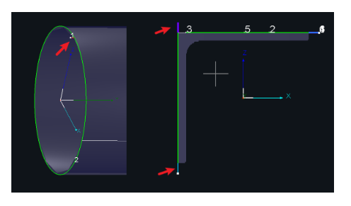
| Angle with X-axis |
Determines the direction of the lead-in start point on the cutting face. From the front view of the tube (as shown in the illustration):
|
| Change Lead on holes |
Checked: Changes the start point of the hole while setting the lead-in. Unchecked: Adds the lead-in at the hole’s original start point. |
| Far End / Near End |
Defined by the Y-axis:
|
| Long Edge / Vertex |
Defined by relative position:
|
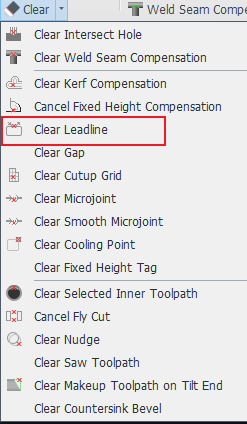
4. Clean Leadline
Ⅲ. FAQS
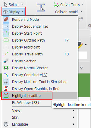
1. How to better distinguish between leadline and Tool path?
Check 【Highlight Leadline】 in 【Display】, and the off-board introduction will become blue, off-board introduction will become purple, and normal leads will become red.
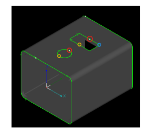
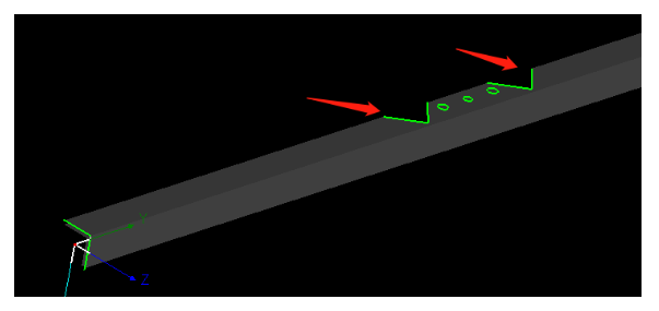
2. Can external leadline and standard leadline be substituted for each other?
When it is necessary to introduce from outside the board, it is necessary to use the external leadline, not the standard leadline, otherwise the cutting direction may be problematic!
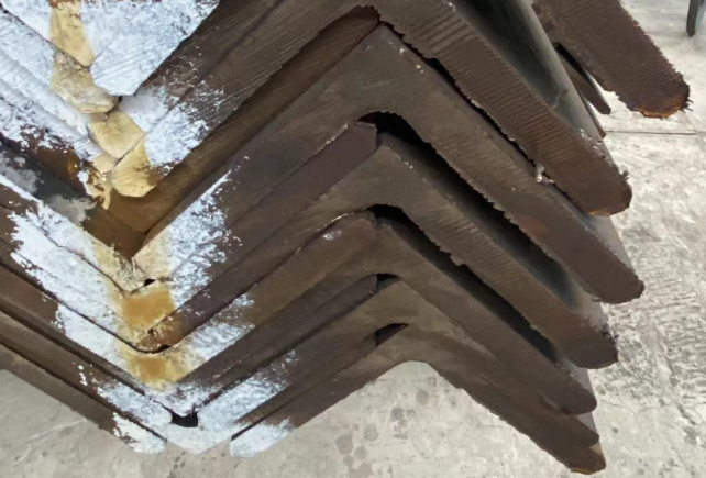
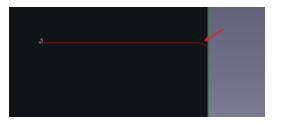
For example, a hole in the face of an angle section like the one in the picture below, where the cut is made from the edge, requires the use of an out-of-plate introduction line.
3. Can I add leadline in TubePro?
Since TubePro has only standard leadline, they must be added in TubesT. It is recommended to add the leadline to the part first and then nest.
I. Introduction
What should be done when poor cutting quality during piercing results in slag that affects the lead-in, or when slag forms due to deceleration and increased laser energy during lead-out? — Add a lead line.
In TubesT, there are two types of lead-in lines: Standard Lead line and External Lead line.
| Standard Lead Line | External Lead Line | |
| Used for closed-section tubes and regular tube surface holes. | Used for sheet steel sections (such as angle steel, channel steel, I-beams) and flange holes. | |
| Lead-in |
Features & Cutting Process:
|
Features & Cutting Process:
|
| Lead-out |
Features & Cutting Process: Scenario (Standard Lead-out):
Note: Do not place a lead-out line on the left cutting path of a part to avoid cutting air (missing the intended cut). |
Features & Cutting Process: Scenario (External Lead-out):
|
Ⅱ. How to use
Note: <>, 【】 in the contents of the tutorial links can be jumped, click on the link, you can view the function corresponding to the detailed parameters of the description, the use of the method.
1. Automatically added
| Standard Lead Line | External Lead Line |
|
Before importing parts, turn on 【Lead】 in 【Auto Technique】.
|
When importing parts, set the length of the off-board leads in 【Import Parameters】. Note: Once set here, the lead length of the part drawn in the software will be this value. Note: If the end face of your part is rounded, you can set the angle of the off-board lead in 【Corrected Y-axis angle】.
|
2. Add manually
| Standard Lead Line | External Lead Line |
|
After importing the part, click [Lead] in the toolbar.
|
After importing the part, set the length of the off-board lead in 【Profile Toolpath】.
|
Note that when the toolpath is a Profile Toolpath, you have to use the method in the 【Profile Toolpath】tutorial to add off-board leads;
When you want to add an off-board lead to an ordinary flange hole (a flange hole without a notch, that is, a non-special toolpath), you can add an off-board lead directly in the drop-down button of the main interface 【Lead】, as shown in the following example.
How to determine whether it is a special toolpath? -Select the toolpath, see whether the toolbar 【Profile Toolpath】 button is lit up, lit up is a special toolpath, if grayed out is an ordinary toolpath.
3. Parameter interpretation.
Parameter |
Interpretation. |
| Line Type |
There are three types available. The effect of using a Straight + Arc lead-in is shown in the figure below.
|
| Angle | The angle between the lead-in and the cutting path. |
| Length | The length of the lead-in. |
| Add at leadin(Lead-in Cooling Point) | Automatically adds a cooling point at the end of the lead-in. |
| Joint Lead |
Continuous Cutting
|
| Lead-out Line |
When processing tubes, due to gravity, the part may fall before the cutting path is complete. This can cause the laser to hit the part directly before finishing the cut, resulting in burn marks and affecting the part’s appearance. Setting a lead-out line helps prevent such thermal damage. |
| Lead on cutoff section |
Checked: Changes the start point on the cutting face while setting the lead-in. Unchecked: The lead-in is added to the original start point of the cutting line. |
| Angle with X-axis |
Determines the direction of the lead-in start point on the cutting face. From the front view of the tube (as shown in the illustration):
|
| Change Lead on holes |
Checked: Changes the start point of the hole while setting the lead-in. Unchecked: Adds the lead-in at the hole’s original start point. |
| Far End / Near End |
Defined by the Y-axis:
|
| Long Edge / Vertex |
Defined by relative position:
|
4. Clean Leadline
Ⅲ. FAQS
1. How to better distinguish between leadline and Tool path?
Check 【Highlight Leadline】 in 【Display】, and the off-board introduction will become blue, off-board introduction will become purple, and normal leads will become red.
2. Can external leadline and standard leadline be substituted for each other?
When it is necessary to introduce from outside the board, it is necessary to use the external leadline, not the standard leadline, otherwise the cutting direction may be problematic!
For example, a hole in the face of an angle section like the one in the picture below, where the cut is made from the edge, requires the use of an out-of-plate introduction line.
3. Can I add leadline in TubePro?
Since TubePro has only standard leadline, they must be added in TubesT. It is recommended to add the leadline to the part first and then nest.

