-
Products
Overview Products
-
2D Cutting
-
Tube Cutting
-
3D Cutting
-
Intelligent Welding
-
Intelligent Cutting Head
-
Industrial Automation
-
Industrial Software
-
Combination
-
Combination
BOCHU New Product -
Combination
BOCHU New Product -
Controller
BOCHU New Product -
2D Cutting Head
Tube Cutting Head
3D Cutting Head
Consumables
BOCHU New Product -
Servo
BOCHU New Product -
Industrial 4.0
-
- Support
- About
- Online Store


- Software Download
- Manual
- Video
- Tutorial
Ⅰ. Introduction
The Intersect Hole feature is a graphical process within TubesT that fixes the angle of the B-axis normal vector during toolpath generation.
For instance, when cutting holes in circular tubular components, the B-axis angle remains variable during standard cutting. This results in the inner wall dimensions being smaller than the outer wall, causing interference during assembly.
Upon applying the Intersect Hole feature, the B-axis remains stationary during circular hole cutting. Consequently, the inner wall dimensions match the outer wall, enabling seamless component assembly.
Note: The content in blue text are all clickable tutorial links. Clicking these links will display detailed explanations corresponding to the respective functions.
II. Usage
1. Function Location
Click the 【Intersect Holes】 dropdown menu at the top of the software to access three types of intersecting hole functions.
2. Precautions
When applying the 【Intersect Holes】 function to circular holes in round pipes, ensure the hole diameter is less than one-third of the pipe's diameter.
3. Operational Steps
(1) Manual Addition
① Select the toolpath or part, then click [IntersecHole].
Note: To set horizontal/vertical intersecting holes, select from the [Intersect Hole] dropdown menu.
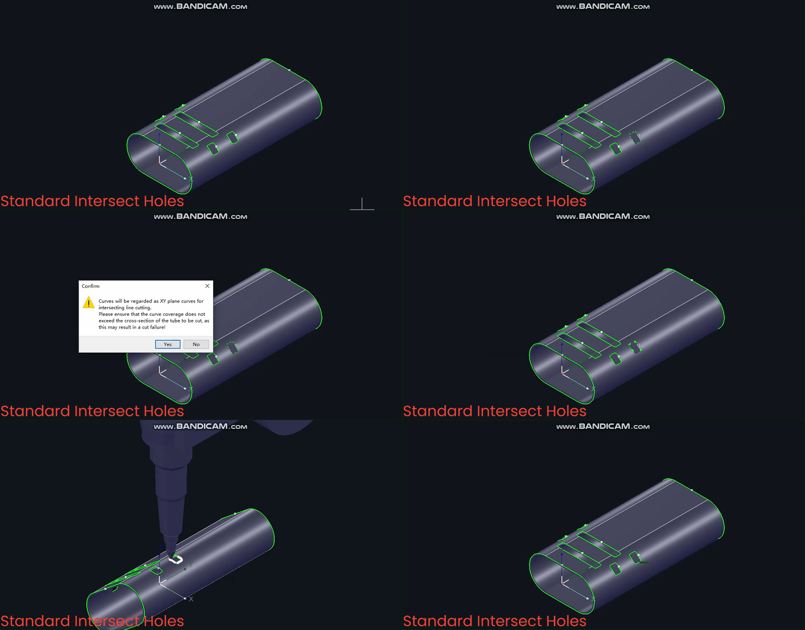
② After setting [Standard Intersect Hole], a prompt will appear; click ‘Yes’ to proceed.
(2) Automatic Addition
To automatically add 【Intersect Holes】 to all pipe surfaces upon part import, tick <Enable Auto Intersect Holes> in 【Auto Technique】 before importing.
Note: This automatically adds 【Standard Intersect Holes】.
4. Functional Effects
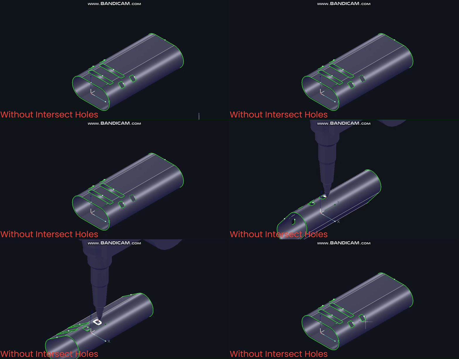
Without 【Intersecting Holes】, pipes rotate during cutting with constantly changing B-axis angles.
(1) 【Standard Intersecting Holes】
Centred on the circle's centre, the toolpath normal vector remains constant throughout. Note: 【Standard Intersecting Holes】 is the most commonly used option.
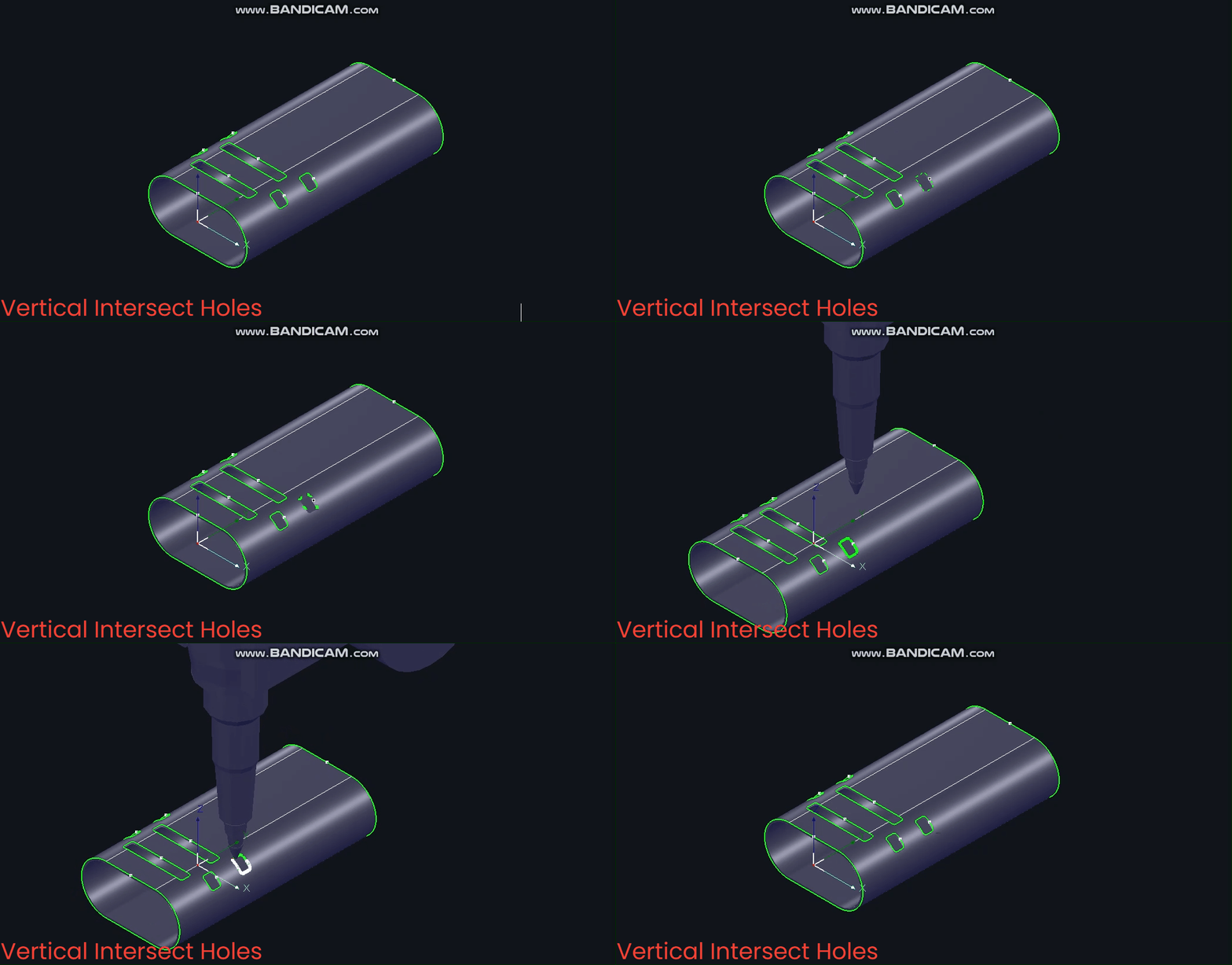
(2) 【Vertical Intersecting Holes】
Based on the Z-axis, the B-axis angle remains fixed at 0° during machining.
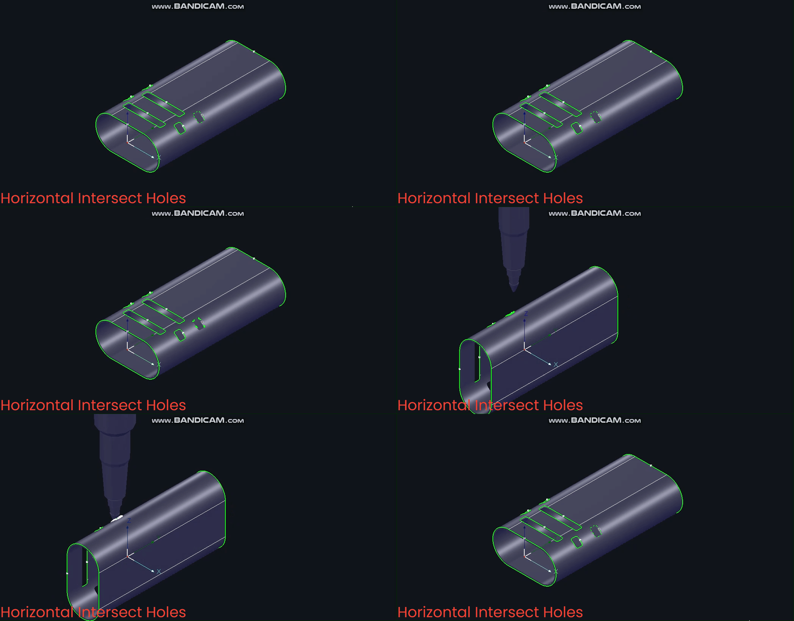
(3) 【Horizontal Intersecting Hole】
Based on the X-axis, the B-axis angle remains constant at ±90° during machining.
5. Additional Techniques
(1) Toolpath Display:
After adding the 【Intersecting Hole】 function to the toolpath, the toolpath lines will be thickened.
(2) Toolpath Normal Vector
Selecting 【Display → Show Normal Vector】 also reveals changes in the toolpath normal vector after adding 【Intersect Holes】.
III. FAQS
1. When the circular hole diameter exceeds one-third of the circular tube diameter, and the 【Intersecting Holes】 function cannot be used, how can interference issues from inserted hole splicing be avoided?
Employ the 【Inner Contour】 function. Refer to the 《process for drilling circular holes in round tubes for details》.
2. What other common applications exist for the 【Intersect Hole】 function?
① Processing intersect holes in slots connected by cut lines ;
② Adding sideways-cut intersect holes for stove-related components.


