-
Products
Overview Products
-
2D Cutting
-
Tube Cutting
-
3D Cutting
-
Intelligent Welding
-
Intelligent Cutting Head
-
Industrial Automation
-
Industrial Software
-
Combination
-
Combination
BOCHU New Product -
Combination
BOCHU New Product -
Controller
BOCHU New Product -
2D Cutting Head
Tube Cutting Head
3D Cutting Head
Consumables
BOCHU New Product -
Servo
BOCHU New Product -
Industrial 4.0
-
- Support
- About
- Online Store


- Software Download
- Manual
- Video
- Tutorial
Ⅰ. Introduction
There are two scenarios where machining nested contours on pipe surfaces is required. Click the jump links in the table to quickly access relevant tutorials.
| Scenarios | Example | Quick Jump |
| (1) Machining a flat part from the scrap area around the hole |  |
Draw in Solidworks |
| (2) An outer toolpath for marking, an inner toolpath for cutting the hole |  |
Draw in Tubest |
II. Operating Instructions
1.Draw in Solidworks
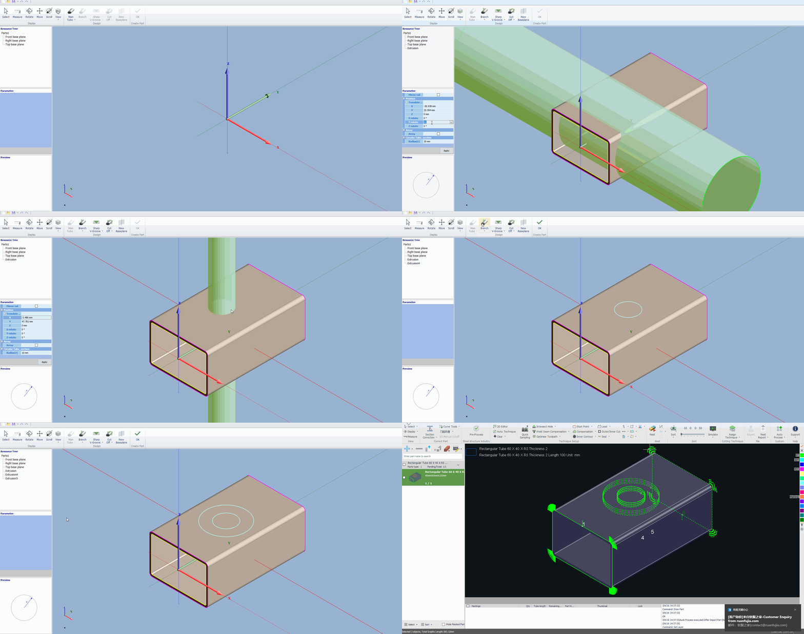
When drawing, place the sheet metal part within the scrap area of the part's inner hole. When importing into TubesT, check the 【in-part shape】 option to generate the corresponding toolpath.
For Scenario (2):
Marking lines can be created using SolidWorks' “Split Line” feature (drawn as a split line + extruded cutout) or imported using the in-part shape method from Method 1 (drawn as a nested hole part).
Both methods will generate two toolpath layers after part import. Crucially, place the marking toolpath on a separate layer with a distinct color. Within the machining software, you can then configure different processing parameters for the green layer (cutting) and the blue layer (marking).
2.Draw in Tubest
The drawing method is consistent. Simply set all nested holes as marking toolpaths during drawing. After completing the part drawing, return to the main interface and assign the corresponding toolpaths to the correct layers.
Note: The marking feature requires TubesT version 7.1.41 or later. For version details, see: TubesT and TubePro Version Comparison
III.FAQS
1. What should I do if the toolpath for nested holes cannot be recognized?
The cause is incorrect drawing methods. After drawing, stretching, and trimming, the surfaces of the round and square holes are not flush, preventing recognition of the round hole toolpath:
Use the correct drawing method (refer to the previous section):
2. What if the nesting software is version 7.1.41 or earlier, lacks marking functionality, and cannot be upgraded?
Use the 【Micro-Shift】 function.
Example: Need to draw nested holes at y=55 as shown in the figure.
When drawing the part, move the outer contour outside the inner hole.
After generating the part, use the <Nudge Graphic> tool under Curve Tools to move the outer hole -30mm in the Y direction.
*In version 7.1.37 and earlier, 【Micro-Shift】 is located in the 【Optimize】 dropdown menu.
If the outer hole is a marking toolpath, select the toolpath and change it to the marking layer.
Adjust the tool sequence for the generated part to cut the inner hole first, then the outer hole.
Ⅰ. Introduction
There are two scenarios where machining nested contours on pipe surfaces is required. Click the jump links in the table to quickly access relevant tutorials.
| Scenarios | Example | Quick Jump |
| (1) Machining a flat part from the scrap area around the hole |  |
Draw in Solidworks |
| (2) An outer toolpath for marking, an inner toolpath for cutting the hole |  |
Draw in Tubest |
II. Operating Instructions
1.Draw in Solidworks
When drawing, place the sheet metal part within the scrap area of the part's inner hole. When importing into TubesT, check the 【in-part shape】 option to generate the corresponding toolpath.
For Scenario (2):
Marking lines can be created using SolidWorks' “Split Line” feature (drawn as a split line + extruded cutout) or imported using the in-part shape method from Method 1 (drawn as a nested hole part).
Both methods will generate two toolpath layers after part import. Crucially, place the marking toolpath on a separate layer with a distinct color. Within the machining software, you can then configure different processing parameters for the green layer (cutting) and the blue layer (marking).
2.Draw in Tubest
The drawing method is consistent. Simply set all nested holes as marking toolpaths during drawing. After completing the part drawing, return to the main interface and assign the corresponding toolpaths to the correct layers.
Note: The marking feature requires TubesT version 7.1.41 or later. For version details, see: TubesT and TubePro Version Comparison
III.FAQS
1. What should I do if the toolpath for nested holes cannot be recognized?
The cause is incorrect drawing methods. After drawing, stretching, and trimming, the surfaces of the round and square holes are not flush, preventing recognition of the round hole toolpath:
Use the correct drawing method (refer to the previous section):
2. What if the nesting software is version 7.1.41 or earlier, lacks marking functionality, and cannot be upgraded?
Use the 【Micro-Shift】 function.
Example: Need to draw nested holes at y=55 as shown in the figure.
When drawing the part, move the outer contour outside the inner hole.
After generating the part, use the <Nudge Graphic> tool under Curve Tools to move the outer hole -30mm in the Y direction.
*In version 7.1.37 and earlier, 【Micro-Shift】 is located in the 【Optimize】 dropdown menu.
If the outer hole is a marking toolpath, select the toolpath and change it to the marking layer.
Adjust the tool sequence for the generated part to cut the inner hole first, then the outer hole.


