

-
Products
Overview Products

-
2D Cutting
-
Tube Cutting
-
3D Cutting
-
Intelligent Welding
-
Intelligent Cutting Head
-
Industrial Automation
-
Industrial Software
-
Combination
-
Combination
BOCHU New Product -
Combination
BOCHU New Product -
Controller
BOCHU New Product -
2D Cutting Head
Tube Cutting Head
3D Cutting Head
Consumables
BOCHU New Product -
Servo
BOCHU New Product -
Industrial 4.0
-
- Support
- About
- Online Store


- Software Download
- Manual
- Video
- Tutorial
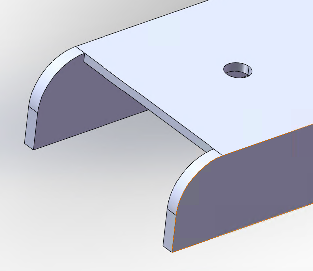
I. Introduction
When joining Channel Sections, if the toolpaths are not properly processed, the two legs may not be cut through, or the desired shape may not be achieved. To ensure normal cutting, please refer to the methods in this guide.
II. Solutions
Different methods are available for different scenarios.
*You can locate the required tutorial based on features or click the corresponding link to jump to the specific section.
| Version | Feature & Link |
| 2025V3.9 and above | |
| Versions earlier than 2025V3.9 |
III. Operation Videos
1. LC Tailoring
Steps:
① Click Nest. The software performs an LC Tailor Check. A prompt will appear, and an exclamation mark will be displayed on the part (as shown).


③ Done.

2. Custom Profile Toolpath (Section Toolpath)
Video Tutorial:
Steps:
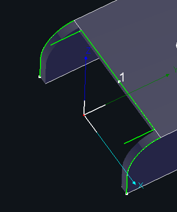
① Use Break Curve in Custom Profile Toolpath (Section Toolpath) to adjust the toolpath direction and sequence.

Note: The gap size should be set according to the wall thickness.

③ Select the toolpath, click the Profile Toolpath function, and add a Regular Leadout in the Profile Toolpath interface.
Note: Set the lead length based on actual requirements.


④ Done. The toolpath effect is shown in the image below.
I. Introduction
When joining Channel Sections, if the toolpaths are not properly processed, the two legs may not be cut through, or the desired shape may not be achieved. To ensure normal cutting, please refer to the methods in this guide.
II. Solutions
Different methods are available for different scenarios.
*You can locate the required tutorial based on features or click the corresponding link to jump to the specific section.
| Version | Feature & Link |
| 2025V3.9 and above | |
| Versions earlier than 2025V3.9 |
III. Operation Videos
1. LC Tailoring
Steps:
① Click Nest. The software performs an LC Tailor Check. A prompt will appear, and an exclamation mark will be displayed on the part (as shown).
③ Done.
2. Custom Profile Toolpath (Section Toolpath)
Video Tutorial:
Steps:
① Use Break Curve in Custom Profile Toolpath (Section Toolpath) to adjust the toolpath direction and sequence.
Note: The gap size should be set according to the wall thickness.
③ Select the toolpath, click the Profile Toolpath function, and add a Regular Leadout in the Profile Toolpath interface.
Note: Set the lead length based on actual requirements.
④ Done. The toolpath effect is shown in the image below.

