

-
Products
Overview Products

-
2D Cutting
-
Tube Cutting
-
3D Cutting
-
Intelligent Welding
-
Intelligent Cutting Head
-
Industrial Automation
-
Industrial Software
-
Combination
-
Combination
BOCHU New Product -
Combination
BOCHU New Product -
Controller
BOCHU New Product -
2D Cutting Head
Tube Cutting Head
3D Cutting Head
Consumables
BOCHU New Product -
Servo
BOCHU New Product -
Industrial 4.0
-
- Support
- About
- Online Store


- Software Download
- Manual
- Video
- Tutorial
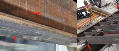
Ⅰ. Overview
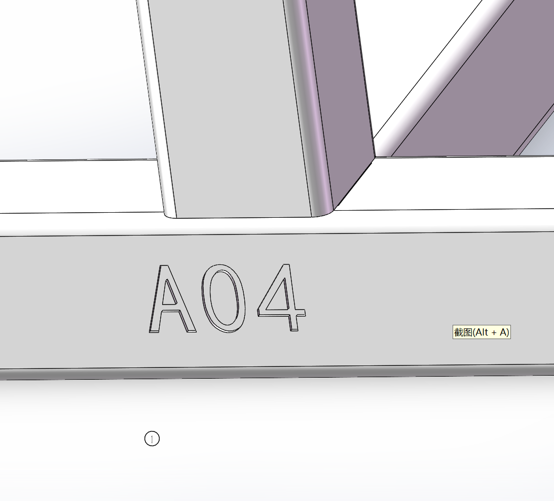
Marking is primarily used to leave traces without cutting through the material. It can be used to mark text or assembly symbols.
When marking is required, first set the marking toolpath in TubesT nesting software to a layer color distinct from the cutting toolpath (typically defaulting to orange).
Then, in TubePro or FACut cutting software, configure different cutting parameters for each layer to achieve either full-penetration or non-penetration effects.
To modify the color of the marking layer, select your marking layer in the 【Technique Classification】 layer settings.

Depending on the type, you can click the link to quickly jump to the desired tutorial:
(Note: After clicking to jump, scroll up slightly with your mouse wheel. After scrolling, you'll see the corresponding subheading.)
| Type | Icon | Quick Jump |
| Text | 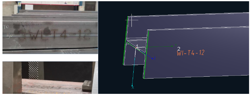 |
Add Marking Text |
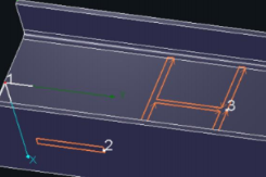
| Assembly Mark | 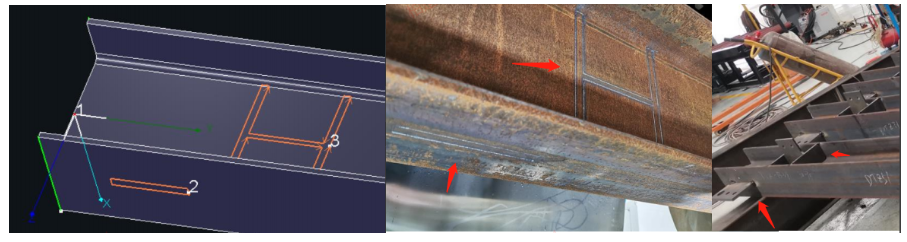 |
Add Assembly Mark |
Ⅱ. How to use
Note: The content in blue are clickable tutorial links. Click the link to view detailed parameter descriptions and usage methods for the corresponding functions.
| Drawing Source | Scene | Schematic Diagram | Corresponding Tutorial |
|
SolidWorks, UG, and other CAD software Tekla modeling software No format restrictions |
Original parts lack engraved text Desire to automatically engrave part names onto part bodies during import |
 |
《Auto Add Text》 |
|
Original parts lack printed marking text Desire to batch-mark any text onto part bodies after importing parts |
《Batch Add Text》 | ||
|
Original parts lack printed marking text Desire to individually mark any text onto part bodies after importing parts |
《Manual Add Text》 | ||
|
SolidWorks, UG, and other CAD software SAT, STEP formats |
Original parts already have drawn marking text Want to batch recognize the drawn text as a marking layer after importing parts |
 |
《Layer Mapping》 |
|
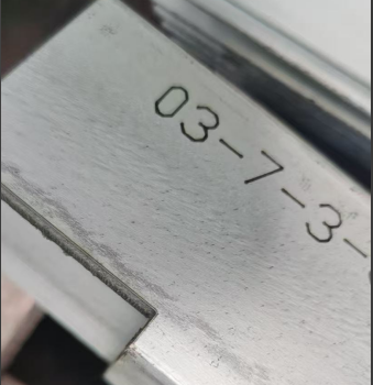
Tekla modeling software NC1 format |
Want to stamp text markings corresponding to assembly stamps onto the part body |  |
《How to export NC1 format parts in Tekla》 In 【User Settings】→【Usage Habits】→【Marking NC1 Steel Stamp】 |
| Drawing Source | Scene | Schematic Diagram | Corresponding Tutorial |
|
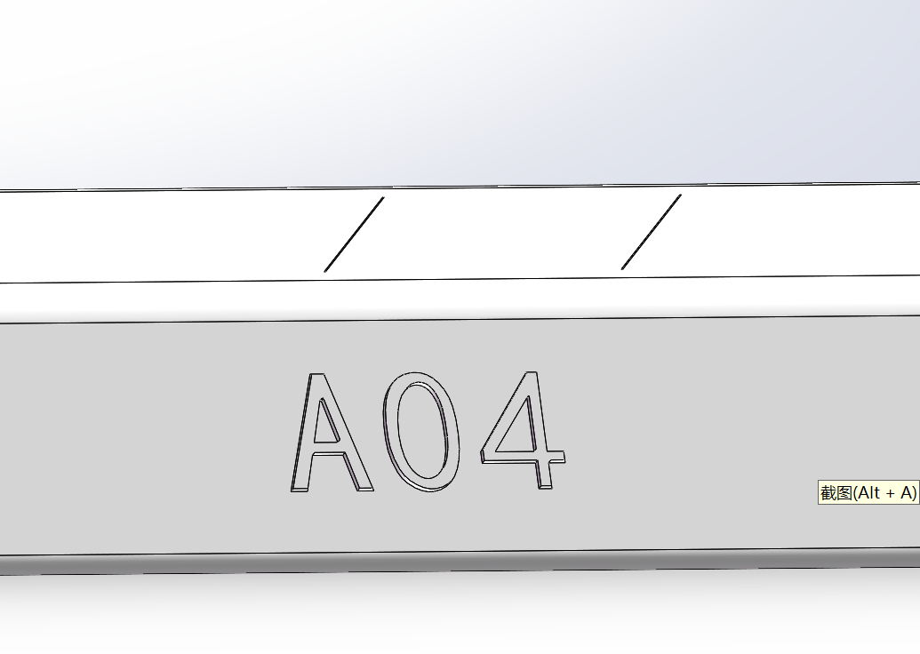
SolidWorks, UG, and other CAD software SAT, STEP formats |
The original part has been drawn with marking lines. After importing the part, I want to batch-identify the drawn marks as a marking layer. |
|
Note: When drawing, it is recommended that the marking outline does not overlap with the part's skeleton lines (e.g., solid lines at R corners). |
| Tekla modeling software |
The original model has been marked with engraving lines. After importing the part, I want to batch-identify the drawn marks as engraving layers. |
 |
《CypWizard Plugin Installation and Usage Tutorial》 When exporting from the plugin, check the 【Mark Welding Position】option.
|
| Drawing within TubesT |
Drawing in TubesT software, intending to set specific toolpaths for marking
|
|


If none of the above conditions apply and the part has already been imported, to modify the toolpath for marking: In the 【Select】, choose the feature you wish to alter and manually set its layer color to the color designated for preparing marking process parameters.
3. Setting Process Parameters
After separating the layer colors for marking and cutting, perform nesting and sorting operations. Once nesting is complete, export the ZX machining file to the cutting software for process parameter configuration.
The main interface of TubePro is shown below. Click 【Technique】 to set the required process parameters for the corresponding layer.

For example, for 1500W-3000W carbon steel, the marking process can be fine-tuned based on the parameters shown below.

Ⅰ. Overview
Marking is primarily used to leave traces without cutting through the material. It can be used to mark text or assembly symbols.
When marking is required, first set the marking toolpath in TubesT nesting software to a layer color distinct from the cutting toolpath (typically defaulting to orange).
Then, in TubePro or FACut cutting software, configure different cutting parameters for each layer to achieve either full-penetration or non-penetration effects.
To modify the color of the marking layer, select your marking layer in the 【Technique Classification】 layer settings.
Depending on the type, you can click the link to quickly jump to the desired tutorial:
(Note: After clicking to jump, scroll up slightly with your mouse wheel. After scrolling, you'll see the corresponding subheading.)
| Type | Icon | Quick Jump |
| Text | |
Add Marking Text |
| Assembly Mark | |
Add Assembly Mark |
Ⅱ. How to use
Note: The content in blue are clickable tutorial links. Click the link to view detailed parameter descriptions and usage methods for the corresponding functions.
| Drawing Source | Scene | Schematic Diagram | Corresponding Tutorial |
|
SolidWorks, UG, and other CAD software Tekla modeling software No format restrictions |
Original parts lack engraved text Desire to automatically engrave part names onto part bodies during import |
|
《Auto Add Text》 |
|
Original parts lack printed marking text Desire to batch-mark any text onto part bodies after importing parts |
《Batch Add Text》 | ||
|
Original parts lack printed marking text Desire to individually mark any text onto part bodies after importing parts |
《Manual Add Text》 | ||
|
SolidWorks, UG, and other CAD software SAT, STEP formats |
Original parts already have drawn marking text Want to batch recognize the drawn text as a marking layer after importing parts |
|
《Layer Mapping》 |
|
Tekla modeling software NC1 format |
Want to stamp text markings corresponding to assembly stamps onto the part body | |
《How to export NC1 format parts in Tekla》 In 【User Settings】→【Usage Habits】→【Marking NC1 Steel Stamp】 |
| Drawing Source | Scene | Schematic Diagram | Corresponding Tutorial |
|
SolidWorks, UG, and other CAD software SAT, STEP formats |
The original part has been drawn with marking lines. After importing the part, I want to batch-identify the drawn marks as a marking layer. |
|
Note: When drawing, it is recommended that the marking outline does not overlap with the part's skeleton lines (e.g., solid lines at R corners). |
| Tekla modeling software |
The original model has been marked with engraving lines. After importing the part, I want to batch-identify the drawn marks as engraving layers. |
|
《CypWizard Plugin Installation and Usage Tutorial》 When exporting from the plugin, check the 【Mark Welding Position】option.
|
| Drawing within TubesT |
Drawing in TubesT software, intending to set specific toolpaths for marking
|
|
If none of the above conditions apply and the part has already been imported, to modify the toolpath for marking: In the 【Select】, choose the feature you wish to alter and manually set its layer color to the color designated for preparing marking process parameters.
3. Setting Process Parameters
After separating the layer colors for marking and cutting, perform nesting and sorting operations. Once nesting is complete, export the ZX machining file to the cutting software for process parameter configuration.
The main interface of TubePro is shown below. Click 【Technique】 to set the required process parameters for the corresponding layer.
For example, for 1500W-3000W carbon steel, the marking process can be fine-tuned based on the parameters shown below.

