

-
Products
Overview Products

-
2D Cutting
-
Tube Cutting
-
3D Cutting
-
Intelligent Welding
-
Intelligent Cutting Head
-
Industrial Automation
-
Industrial Software
-
Combination
-
Combination
BOCHU New Product -
Combination
BOCHU New Product -
Controller
BOCHU New Product -
2D Cutting Head
Tube Cutting Head
3D Cutting Head
Consumables
BOCHU New Product -
Servo
BOCHU New Product -
Industrial 4.0
-
- Support
- About
- Online Store


- Software Download
- Manual
- Video
- Tutorial
I. Overview
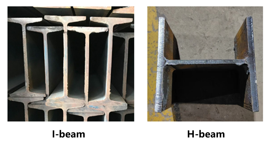
I-beam and H-steel are the most common tubular types in the steel structure industry.
For this industry, BOCHU has launched a five-in-one processing solution for shaped steel, among which the tube nesting software TubesT-H has been optimized for various personalized scenarios in the steel structure industry.
Note: The content in 【】or [] is all tutorial links that can be jumped to. Clicking the link allows you to view the detailed parameter description and usage method corresponding to the function.
If you still have unresolved issues after reading this tutorial, please click on the "![]() " in the upper left corner of the software, scan the QR code on the left to enter the official nesting exchange group.
" in the upper left corner of the software, scan the QR code on the left to enter the official nesting exchange group.
Pink bold text indicates function documentation notes, for which the English version is currently unavailable.
II. Foundational General Knowledge
Before starting the operation, please make sure you have read the 【What is TubesT?】 and understand the role of the nesting software in the entire processing flow, as well as the usage methods of various file formats and the meanings of version types.
TubesT-H Tubular Restrictions:
① H-beam, (hot-rolled) angle steel, (hot-rolled) channel steel, T-beam.
② From Version 25V3, supports automatic identification of round, square and rectangular tubes
FACut-H Version Limitations :TubesT - The version of TubesT corresponding to FACUT-H(9200 System)
III. The Nesting Process
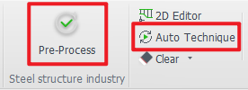
1. Pre-Process and Auto Technique
There are some common operations, such as:
-
-
- Automatically adding marking text to parts (recommended)
- Familiar with some basic processes, want the software to automatically add leader lines and compensation to tube holes (recommended)
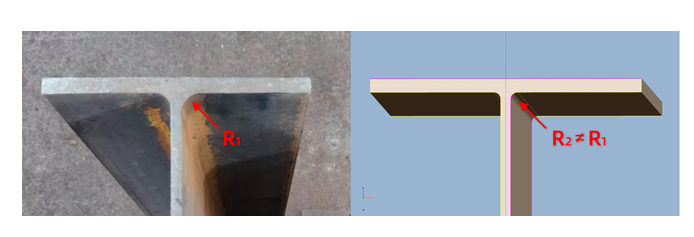
- When the actual R corner size of the I-beam is inconsistent with the drawing, you want to automatically modify the R corner (supports t2t, x2t, nc1 formats of H-beam)
- Want to automatically add gaps to parts (When maintaining the integrity of the tube for ease of clamping)
-
These can be configured in advance in 【Auto Technique】and 【Pre-process】 before importing parts.
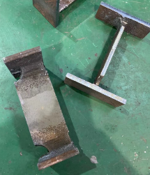
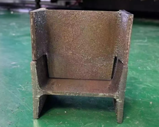
After importing the parts, check all parts. Some effects are shown in the example:

2. Get the parts
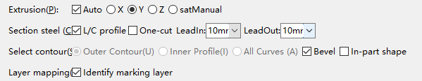
The recommended import parameters are as follows, where the Bevel checkbox can be selected as needed:
| Source | Format | Tutorials (Mandatory to Watch) |
|
Tekla |
t2t, x2t, ifc, nc1 and etc. |
|
|
TubesT - Quick Sanpling
|
jhb, jhbs and etc. |
[Quick Sampling: H-Beam Bevel and Web Weld Scallop] [Quick Sampling: H-Beam T Joint Style 1,2 and 3] |
|
TubesT - TubeDraw |
jhb, jhbs and etc. | |
| SolidWorks、ug and etc. | igs, sat, step and etc. |
★ If the import fails, you can troubleshoot it based on these experiences: 【How to Resolve Part Import Failed or Recognition Errors】
3. Check the Parts
Before part processing, inspect parts to prevent post-nesting discrepancies. Reprocessing erroneous parts consumes significant additional time. Refer to the following checklist:
① Marking
-
-
-
- Is marking text applied?
- Is positioning appropriate?
-
-
② Bevel Integrity Check (For beveled parts)
-
-
-
- Are all bevels correctly identified?
- Does the bevel toolpath achieve intended results?
-
-
③ Toolpath Anomaly Detection
-
-
-
- Missing toolpaths?
- Redundant/extra toolpaths?
-
-
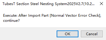
★ If a prompt appears after import: "Normal Vector Error Check", click "OK".
This feature performs toolpath verification on parts identified with bevels. Components containing critical errors will be flagged with yellow warning triangles.
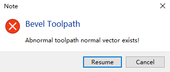
If errors are detected, resolve them by referring to "【Normal Vector Error Detection】- FAQ #1" in the tutorial.
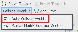
4. Collision-Avoid
During oscillation at the I-beam R-corner cutting zone, the cutting head is prone to collide with the flange plate.
Collision prevention requires mandatory deployment of the cutting head 3D model. Operational Reference: Detailed methodology in 【Manual Modify Contour Vector】.
Users of TubesT-H must exclusively deploy SES 3D Cutting Head models.
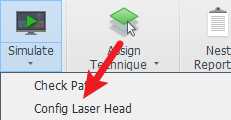
To configure:
Simulate Dropdown Menu → → Select structural steel cutting head model matching the equipment.
-
-
- How to confirm: Locate model label on the cutting head exterior or Contact equipment manufacturer's after-sales service
-
5. Optimize Toolpath
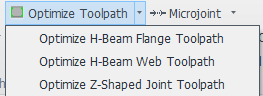
The toolpaths generated from I-beam drawings often exhibit certain discrepancies compared to actual machining requirements. Implementing toolpath optimization is essential to enhance production quality and efficiency.
Operational References:
① Optimize H-beam web toolpath
② Optimize H-Beam Flange Toolpath
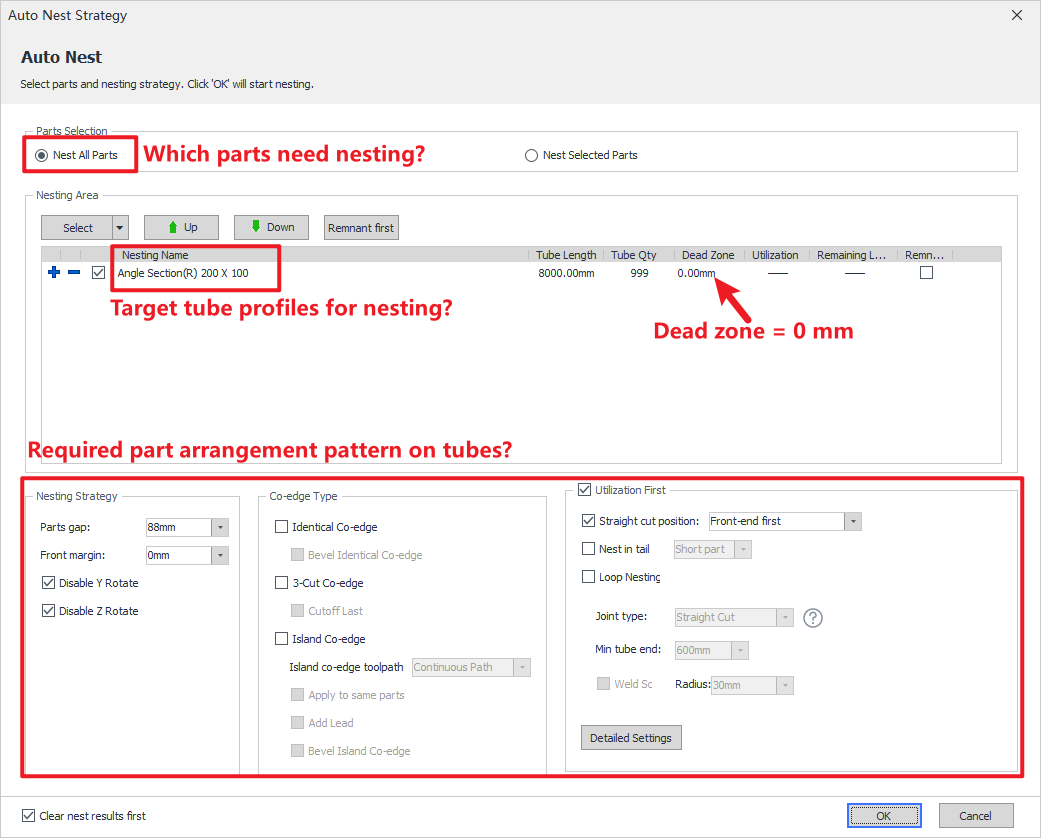
6. Auto-Nest
After completing part inspection, proceed to nesting operations.Reference Tutorial: 【Apply Auto Nest】.
| Common Parameters | Definitions |
| Dead Zone |
The parameter can be directly set to 0 as the default configuration. For special processing requirements, users may manually adjust the parameter value. |
| Front margin |
The parameter can be directly set to 0 as the default configuration. |
| ★ Loop Nesting★ | Core Principle of Nesting. The tutorial is mandatory viewing for all operators. |
| Other Special Settings |
Straight cut position |
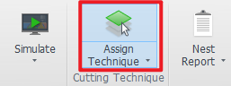
7. Assign Technique
Process differentiation must be performed after nesting completion. Reference Tutorial: 【Assign Technique】.
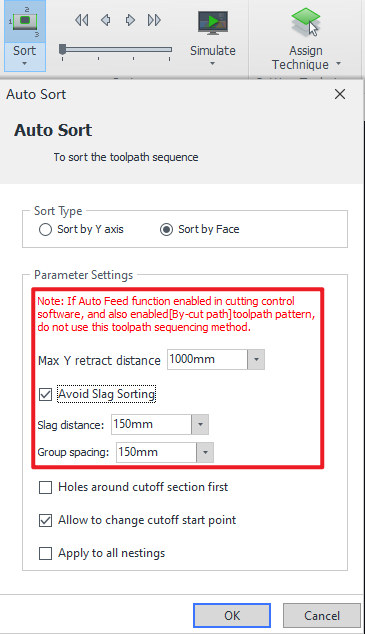
8.Auto-sort (Avoid Slag Sorting)
If high precision is required for web holes and you want to cut the web first before the flanges to prevent flange slag from affecting hole cutting, directly use 【Slag-free Sort】.
In other cases, no special settings are required. For detailed instructions, refer to:【Sort Strategy】.
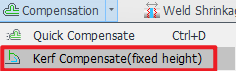
9.Kerf Compensation
Fixed-height cutting is widely applied in flange-proximate toolpaths, including weld access holes and tabs.
Without kerf compensation, these paths may exhibit noticeable notches or – due to excessive kerf width cause toolhead collisions during subsequent path execution.
For constant-height toolpath machining, applying 【Kerf Compensation(fixed height)】 effectively prevents dimensional errors caused by kerf overwidth.
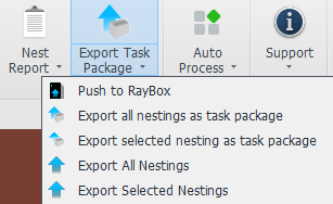
10.Export Task Package
After completing nesting and sequencing operations, you may export the nesting results. Reference tutorial: 【Export】
Additionally, the nesting report can be exported separately. Reference tutorial: 【Report (New in TubesT 7.1.55)】
IV. FAQs
(To be updated...)
I. Overview
I-beam and H-steel are the most common tubular types in the steel structure industry.
For this industry, BOCHU has launched a five-in-one processing solution for shaped steel, among which the tube nesting software TubesT-H has been optimized for various personalized scenarios in the steel structure industry.
Note: The content in 【】or [] is all tutorial links that can be jumped to. Clicking the link allows you to view the detailed parameter description and usage method corresponding to the function.
If you still have unresolved issues after reading this tutorial, please click on the "![]() " in the upper left corner of the software, scan the QR code on the left to enter the official nesting exchange group.
" in the upper left corner of the software, scan the QR code on the left to enter the official nesting exchange group.
Pink bold text indicates function documentation notes, for which the English version is currently unavailable.
II. Foundational General Knowledge
Before starting the operation, please make sure you have read the 【What is TubesT?】 and understand the role of the nesting software in the entire processing flow, as well as the usage methods of various file formats and the meanings of version types.
TubesT-H Tubular Restrictions:
① H-beam, (hot-rolled) angle steel, (hot-rolled) channel steel, T-beam.
② From Version 25V3, supports automatic identification of round, square and rectangular tubes
FACut-H Version Limitations :TubesT - The version of TubesT corresponding to FACUT-H(9200 System)
III. The Nesting Process
1. Pre-Process and Auto Technique
There are some common operations, such as:
-
-
- Automatically adding marking text to parts (recommended)
- Familiar with some basic processes, want the software to automatically add leader lines and compensation to tube holes (recommended)
- When the actual R corner size of the I-beam is inconsistent with the drawing, you want to automatically modify the R corner (supports t2t, x2t, nc1 formats of H-beam)
- Want to automatically add gaps to parts (When maintaining the integrity of the tube for ease of clamping)
-
These can be configured in advance in 【Auto Technique】and 【Pre-process】 before importing parts.
After importing the parts, check all parts. Some effects are shown in the example:
2. Get the parts
The recommended import parameters are as follows, where the Bevel checkbox can be selected as needed:
| Source | Format | Tutorials (Mandatory to Watch) |
|
Tekla |
t2t, x2t, ifc, nc1 and etc. |
|
|
TubesT - Quick Sanpling
|
jhb, jhbs and etc. |
[Quick Sampling: H-Beam Bevel and Web Weld Scallop] [Quick Sampling: H-Beam T Joint Style 1,2 and 3] |
|
TubesT - TubeDraw |
jhb, jhbs and etc. | |
| SolidWorks、ug and etc. | igs, sat, step and etc. |
★ If the import fails, you can troubleshoot it based on these experiences: 【How to Resolve Part Import Failed or Recognition Errors】
3. Check the Parts
Before part processing, inspect parts to prevent post-nesting discrepancies. Reprocessing erroneous parts consumes significant additional time. Refer to the following checklist:
① Marking
-
-
-
- Is marking text applied?
- Is positioning appropriate?
-
-
② Bevel Integrity Check (For beveled parts)
-
-
-
- Are all bevels correctly identified?
- Does the bevel toolpath achieve intended results?
-
-
③ Toolpath Anomaly Detection
-
-
-
- Missing toolpaths?
- Redundant/extra toolpaths?
-
-
★ If a prompt appears after import: "Normal Vector Error Check", click "OK".
This feature performs toolpath verification on parts identified with bevels. Components containing critical errors will be flagged with yellow warning triangles.
If errors are detected, resolve them by referring to "【Normal Vector Error Detection】- FAQ #1" in the tutorial.
4. Collision-Avoid
During oscillation at the I-beam R-corner cutting zone, the cutting head is prone to collide with the flange plate.
Collision prevention requires mandatory deployment of the cutting head 3D model. Operational Reference: Detailed methodology in 【Manual Modify Contour Vector】.
Users of TubesT-H must exclusively deploy SES 3D Cutting Head models.
To configure:
Simulate Dropdown Menu → → Select structural steel cutting head model matching the equipment.
-
-
- How to confirm: Locate model label on the cutting head exterior or Contact equipment manufacturer's after-sales service
-
5. Optimize Toolpath
The toolpaths generated from I-beam drawings often exhibit certain discrepancies compared to actual machining requirements. Implementing toolpath optimization is essential to enhance production quality and efficiency.
Operational References:
① Optimize H-beam web toolpath
② Optimize H-Beam Flange Toolpath
6. Auto-Nest
After completing part inspection, proceed to nesting operations.Reference Tutorial: 【Apply Auto Nest】.
| Common Parameters | Definitions |
| Dead Zone |
The parameter can be directly set to 0 as the default configuration. For special processing requirements, users may manually adjust the parameter value. |
| Front margin |
The parameter can be directly set to 0 as the default configuration. |
| ★ Loop Nesting★ | Core Principle of Nesting. The tutorial is mandatory viewing for all operators. |
| Other Special Settings |
Straight cut position |
7. Assign Technique
Process differentiation must be performed after nesting completion. Reference Tutorial: 【Assign Technique】.
8.Auto-sort (Avoid Slag Sorting)
If high precision is required for web holes and you want to cut the web first before the flanges to prevent flange slag from affecting hole cutting, directly use 【Slag-free Sort】.
In other cases, no special settings are required. For detailed instructions, refer to:【Sort Strategy】.
9.Kerf Compensation
Fixed-height cutting is widely applied in flange-proximate toolpaths, including weld access holes and tabs.
Without kerf compensation, these paths may exhibit noticeable notches or – due to excessive kerf width cause toolhead collisions during subsequent path execution.
For constant-height toolpath machining, applying 【Kerf Compensation(fixed height)】 effectively prevents dimensional errors caused by kerf overwidth.
10.Export Task Package
After completing nesting and sequencing operations, you may export the nesting results. Reference tutorial: 【Export】
Additionally, the nesting report can be exported separately. Reference tutorial: 【Report (New in TubesT 7.1.55)】
IV. FAQs
(To be updated...)

