

-
Products
Overview Products

-
2D Cutting
-
Tube Cutting
-
3D Cutting
-
Intelligent Welding
-
Intelligent Cutting Head
-
Industrial Automation
-
Industrial Software
-
Combination
-
Combination
BOCHU New Product -
Combination
BOCHU New Product -
Controller
BOCHU New Product -
2D Cutting Head
Tube Cutting Head
3D Cutting Head
Consumables
BOCHU New Product -
Servo
BOCHU New Product -
Industrial 4.0
-
- Support
- About
- Online Store


- Software Download
- Manual
- Video
- Tutorial
I. Introduction
What if the slit caused by the laser when cutting affects the size of the part? What should I do if I want to micro-adjust the size of the part? --Use the 【Compensation】 function.
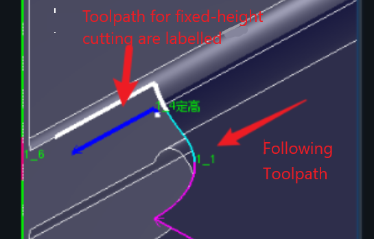
In the actual processing of parts, there are two types of cutting methods, <Following> and <Fixed Height>, in which the cutting slit of the following cutting is small and normal compensation is used, and the cutting slit of the fixed height tool path is large and fixed height compensation should be used.
| Normal Compensation (introduced in this article) | Kerf Compensation(fixed height) (Click on the link to see how to use it) |
|
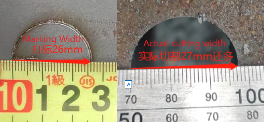
e.g. : Oxygen cutting is a common method used in thick or heavy pipe cutting operations. Due to the large kerf width produced by oxygen cutting, the actual hole diameter cut may be 1-5 mm larger than the dimensions shown on the design drawing, while the overall length of the part may be 2-5 mm shorter than expected. To correct this dimensional deviation, compensation techniques need to be applied to adjust the cutting path with appropriate inward or widening adjustments. |
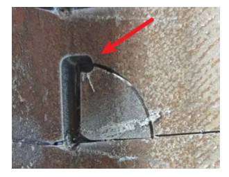
Fixed-height cuts have wider cut seams than follow-throughs. The fixed-height cut is often around 8mm, and the follow-through cut is often around 1mm. If you don't take into account the fixed-height slit compensation, the cutting path will have obvious gaps, or due to the large fixed-height slit, then cutting the following path will lead to head sticking, as shown in the figure below. |
|
  |
Note: Italic texts with blue highlights are clickable tutorial links that lead to detailed parameter explanations and usage instructions.
II. How to Use
1. Automatically added.
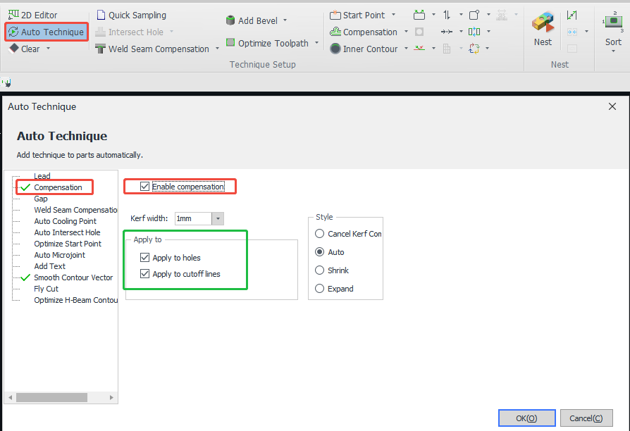
Before importing the part, turn on 【Compensation】 in 【Auto Technique】, note that the compensation here is ordinary compensation, if you want to add height compensation, please operate after the part is imported.
2. Add manually
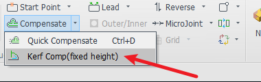
| Normal Compensation (introduced in this article) | Kerf Compensation(fixed height) | |
| Individual Adding |  |
 |
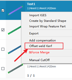
| Batch Adding |
Tick the list of parts, then click the right mouse button for batch setting
|
After clicking Fixed Height Cutting Compensation, range is set directly while setting the parameters.
|
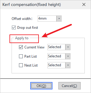
3. Parameter interpretation.
①Compensation value: the compensation value for the hole should be the actual value of the cut out minus half of the theoretical value.
② Effective range: Select the selected toolpath or all toolpaths of the main interface part; and whether it is effective for the cut line or hole in the selected part/toolpath.
③ Style: Inward shrinkage (make smaller) or outward expansion (make larger). Note that for round or square holes on tubes, etc., the actual size of the cutting effect, regardless of inward shrinkage or outward expansion, is compensated by twice the parameter.
④ Corner processing: when the corner is modified into a rounded corner that does not affect the size, the inward concave is rounded, and the outward convex is a right angle, so that in the cutting of the corners, it can effectively reduce burnt edges.
⑤ For a detailed tutorial on the compensation style function: Compensation Expansion Style.
⑥ For detailed parameter explanation of fixed height cut seam compensation, please refer to: Kerf Compensation(fixed height).
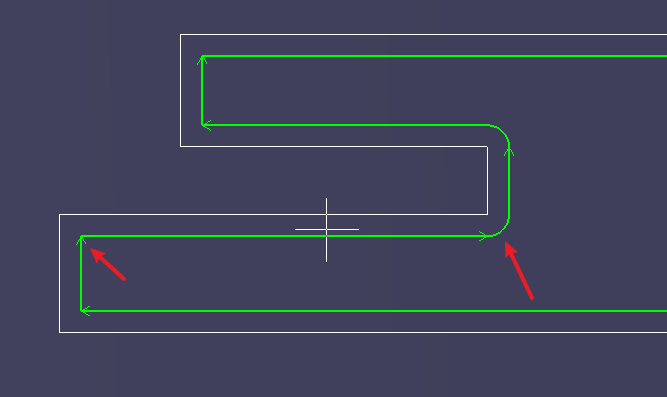
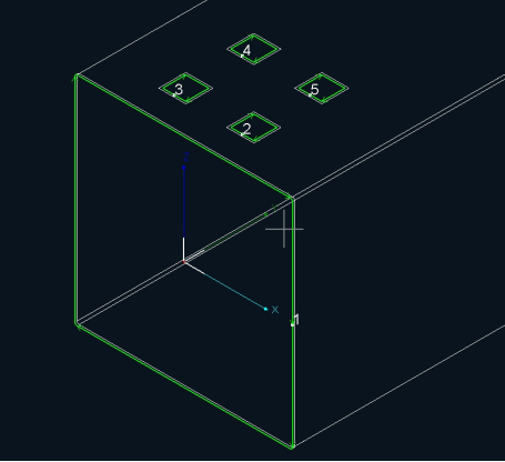
4.Compensation effect.
The original Toolpaths becomes white after compensation, and the compensated Toolpaths becomes green; and there is a certain distance between two knife paths.
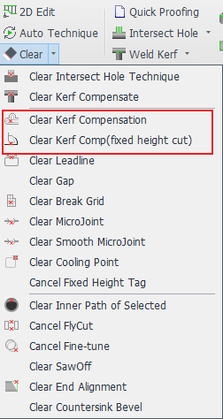
5. Clean Compensation
Ⅲ. FAQS
1. What is the relationship between Compensation and Weld Kerf?
They are two different functions and solve different problems. For a tutorial on the function of weld compensation, please refer to: Weld Kerf.
2. The groove and the cut-off line are connected, how to add different compensation to the notch and the cut-off line?
Refer to 《Add Different Layers for a Single Cutting Path》 tutorial.
I. Introduction
What if the slit caused by the laser when cutting affects the size of the part? What should I do if I want to micro-adjust the size of the part? --Use the 【Compensation】 function.
In the actual processing of parts, there are two types of cutting methods, <Following> and <Fixed Height>, in which the cutting slit of the following cutting is small and normal compensation is used, and the cutting slit of the fixed height tool path is large and fixed height compensation should be used.
| Normal Compensation (introduced in this article) | Kerf Compensation(fixed height) (Click on the link to see how to use it) |
|
e.g. : Oxygen cutting is a common method used in thick or heavy pipe cutting operations. Due to the large kerf width produced by oxygen cutting, the actual hole diameter cut may be 1-5 mm larger than the dimensions shown on the design drawing, while the overall length of the part may be 2-5 mm shorter than expected. To correct this dimensional deviation, compensation techniques need to be applied to adjust the cutting path with appropriate inward or widening adjustments. |
Fixed-height cuts have wider cut seams than follow-throughs. The fixed-height cut is often around 8mm, and the follow-through cut is often around 1mm. If you don't take into account the fixed-height slit compensation, the cutting path will have obvious gaps, or due to the large fixed-height slit, then cutting the following path will lead to head sticking, as shown in the figure below. |
|
|
|
Note: Italic texts with blue highlights are clickable tutorial links that lead to detailed parameter explanations and usage instructions.
II. How to Use
1. Automatically added.
Before importing the part, turn on 【Compensation】 in 【Auto Technique】, note that the compensation here is ordinary compensation, if you want to add height compensation, please operate after the part is imported.
2. Add manually
| Normal Compensation (introduced in this article) | Kerf Compensation(fixed height) | |
| Individual Adding | |
|
| Batch Adding |
Tick the list of parts, then click the right mouse button for batch setting
|
After clicking Fixed Height Cutting Compensation, range is set directly while setting the parameters.
|
3. Parameter interpretation.
①Compensation value: the compensation value for the hole should be the actual value of the cut out minus half of the theoretical value.
② Effective range: Select the selected toolpath or all toolpaths of the main interface part; and whether it is effective for the cut line or hole in the selected part/toolpath.
③ Style: Inward shrinkage (make smaller) or outward expansion (make larger). Note that for round or square holes on tubes, etc., the actual size of the cutting effect, regardless of inward shrinkage or outward expansion, is compensated by twice the parameter.
④ Corner processing: when the corner is modified into a rounded corner that does not affect the size, the inward concave is rounded, and the outward convex is a right angle, so that in the cutting of the corners, it can effectively reduce burnt edges.
⑤ For a detailed tutorial on the compensation style function: Compensation Expansion Style.
⑥ For detailed parameter explanation of fixed height cut seam compensation, please refer to: Kerf Compensation(fixed height).
4.Compensation effect.
The original Toolpaths becomes white after compensation, and the compensated Toolpaths becomes green; and there is a certain distance between two knife paths.
5. Clean Compensation
Ⅲ. FAQS
1. What is the relationship between Compensation and Weld Kerf?
They are two different functions and solve different problems. For a tutorial on the function of weld compensation, please refer to: Weld Kerf.
2. The groove and the cut-off line are connected, how to add different compensation to the notch and the cut-off line?
Refer to 《Add Different Layers for a Single Cutting Path》 tutorial.

