

-
Products
Overview Products

-
2D Cutting
-
Tube Cutting
-
3D Cutting
-
Intelligent Welding
-
Intelligent Cutting Head
-
Industrial Automation
-
Industrial Software
-
Combination
-
Combination
BOCHU New Product -
Combination
BOCHU New Product -
Controller
BOCHU New Product -
2D Cutting Head
Tube Cutting Head
3D Cutting Head
Consumables
BOCHU New Product -
Servo
BOCHU New Product -
Industrial 4.0
-
- Support
- About
- Online Store


- Software Download
- Manual
- Video
- Tutorial
I. Introduction
Generating the toolpathin CAM software is heavily dependent on the correctness of the source CAD model. This tutorial details modeling specifications for parts and examines common modeling pitfalls.
Menu
(1) Mandatory Universal Specifications for All Parts
(2) Square/Rectangular Tubes Guide
(3) Angle & Channel Steel Tubes Guide
(4) I-Beam and H-Beam Tubes Guide
Note:
First review the <Mandatory Universal Specifications for All Parts>, then examine the section-specific considerations for the part you are currently machining. Both sections must be reviewed.
After clicking the Table of Contents, scroll up slightly to locate the corresponding subsection headings.
Pink bold text indicates function documentation notes, for which the English version is currently unavailable.
II. Detailed Specifications
(1)Mandatory Universal Specifications for All Parts
| Requirements | Compliant Modeling | Non-Compliant Modeling |
|
The part cross-sections in drawing = The actual tube section. |
 |
|
|
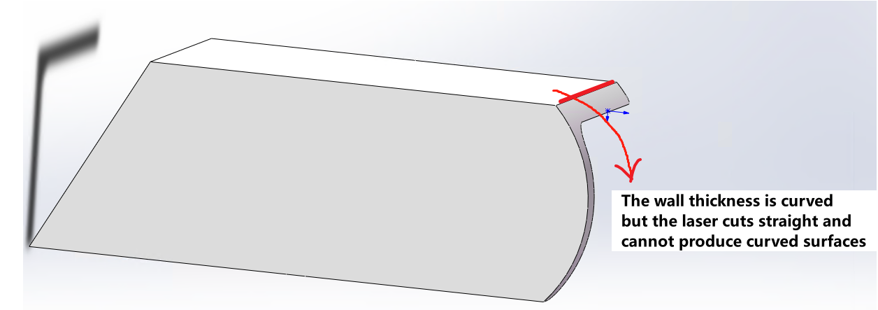
The part must be manufacturable using available machine tool capabilities. |
 |
|
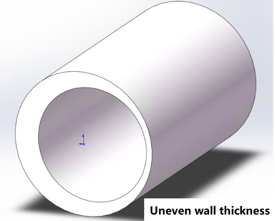
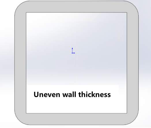
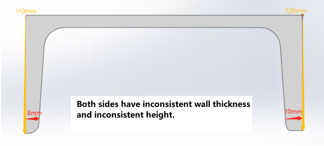
| Thickness must be uniform | 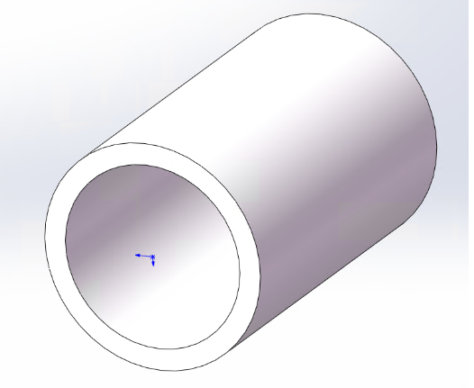 |
 |
|
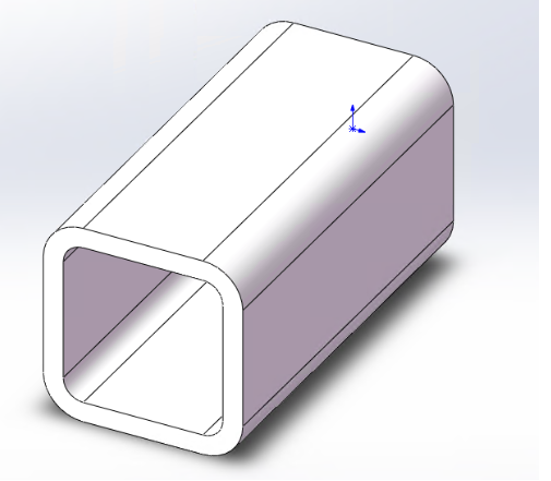
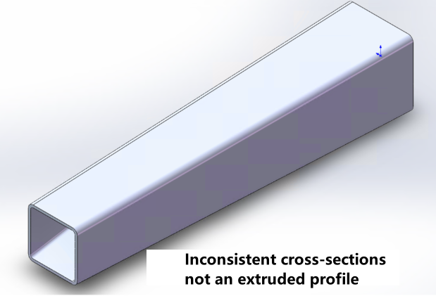
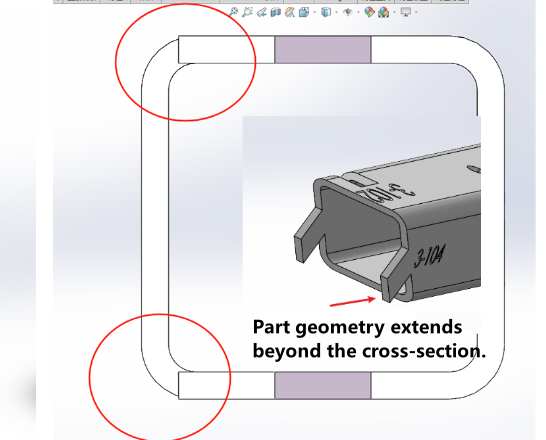
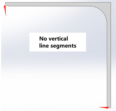
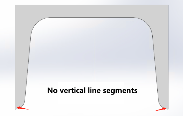
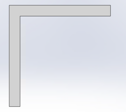
Must be an extruded profile Consistent cross-section at any position No redundant protrusions |
|
|
|
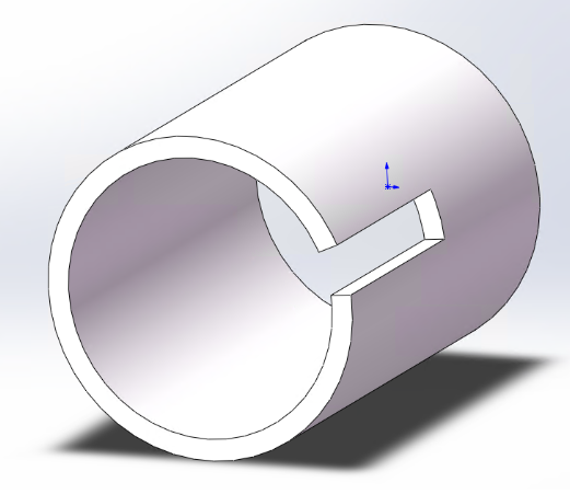
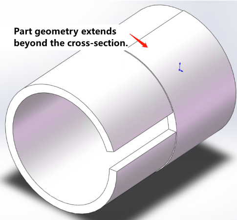
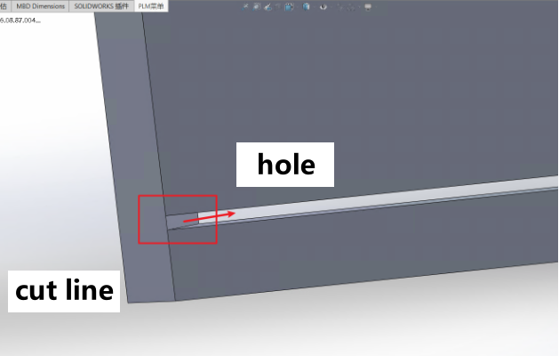
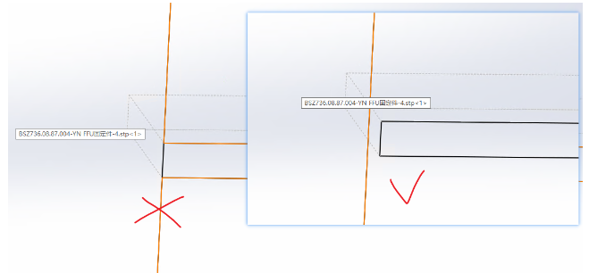
Holes and slots must not intersect with end faces (to prevent toolpath recognition errors). |
|
|
|
Other Quick Links: Square/Rectangular Tubes Guide |
||
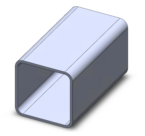
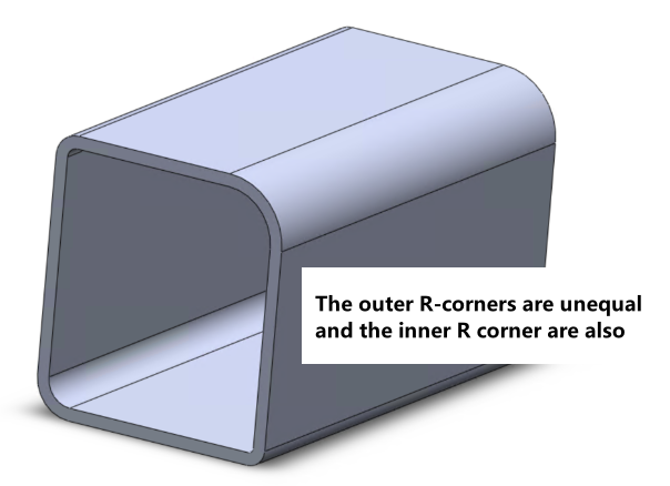
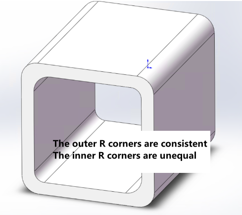
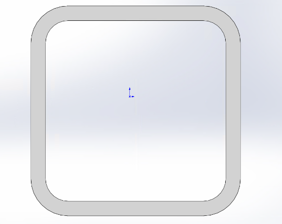
(2)Square/Rectangular Tubes Guide
| Requirements | Compliant Modeling | Non-Compliant Modeling |
|
Internal = external R corner |
|
|
|
External R corner - Thickness = Internal R corner |
|
 |
|
Other Quick Links: Mandatory Universal Specifications for All Parts |
||
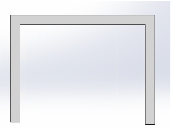
(3)Angle & Channel Steel Tubes Guide
| Requirements | Compliant Modeling | Non-Compliant Modeling |
|
No R corner required |
|
|
|
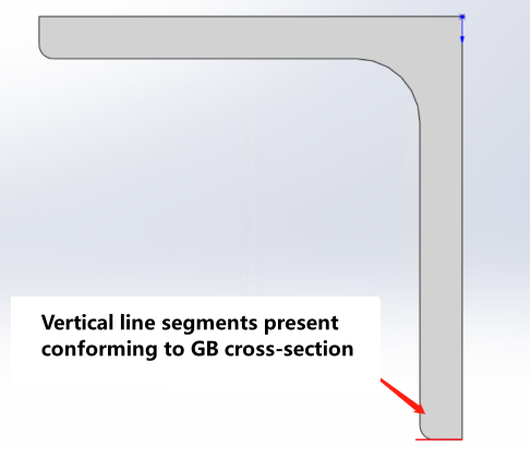
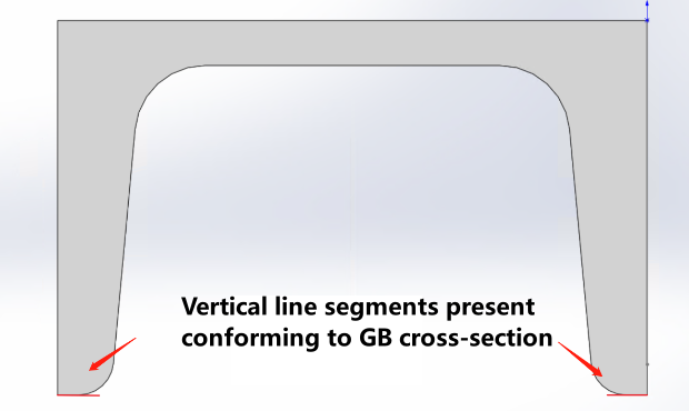
When modeling R corner, you must conform to GB standard types |
|
  |
|
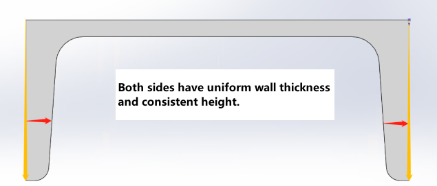
The thickness and length on both sides of channel steel must be uniform. |
|
 |
|
Other Quick Links: Mandatory Universal Specifications for All Parts |
||
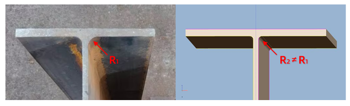
(4)I-Beam and H-Beam Tubes Guide
| Requirements | Compliant Modeling | Non-Compliant Modeling |
|
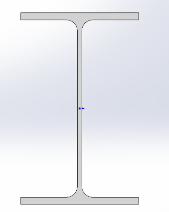
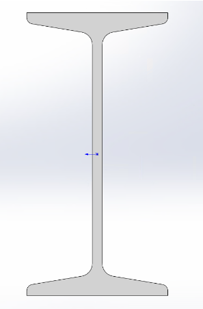
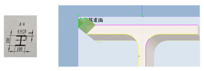
Web R corner cannot be 0 Web must be centered between flanges Top/bottom flange thickness and length must match |
Note: I-beams should be modeled as H-beams, with flange thickness set to the maximum I-beam flange thickness specification. |
Revision Method 【How to Add Fillets to an I-Beam with R=0】 |
|
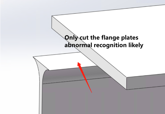
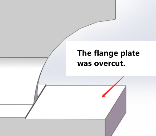
When the wing plate/web is completely unnecessary, an additional portion needs to be cut from another area. |
|
|
|
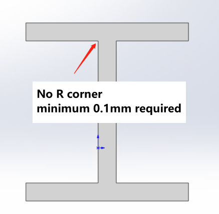
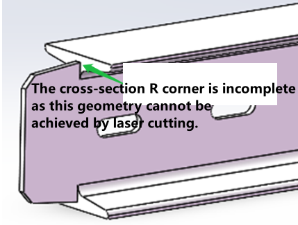
A shape that cannot be directly cut by laser has appeared at the R-corner position. |
※The tongue width needs to be confirmed, as different width requirements lead to different drafting specifications.
|
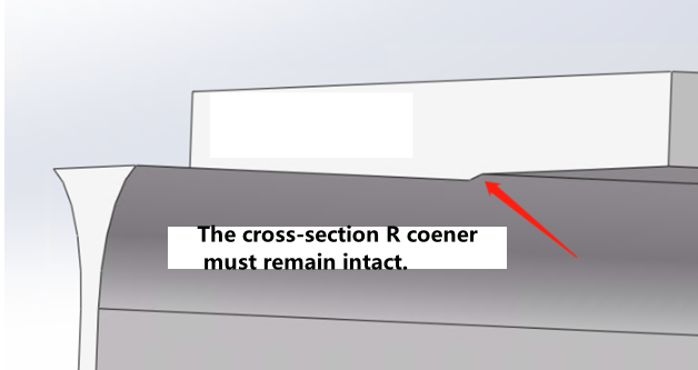
The web R corner must be retained to avoid laser-uncuttable geometries.
|
|
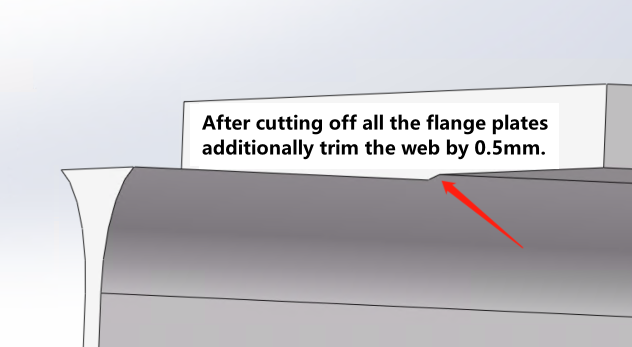
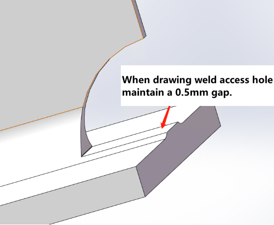
The flange plate shall remain intact, and the web scallop for welding should retain a root (a root of 0.5mm is recommended). |
|
|
|
Other Quick Links: Mandatory Universal Specifications for All Parts Square/Rectangular Tubes Guide |
||
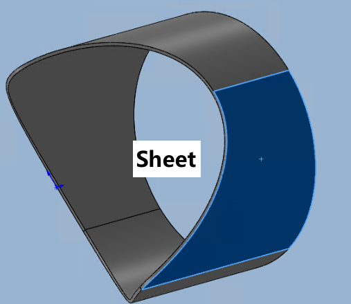
(5)Sheet Metal Parts Guide
| Requirements | Compliant Modeling | Non-Compliant Modeling |
|
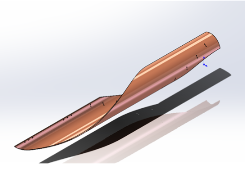
The cross-section of the part is damaged.
|
|
Solution: 【The Solution for Sheet Metal Part Processing】 |
|
|
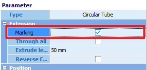
Click [Draw Part], then select the [Folder Icon] in the top-left corner. Import the part and change the extrusion cut feature to [Making] .
Detailed Explanation 【Toolpath Processing Tutorial for Sheet Metal Parts】 |
|
|
Other Quick Links: Mandatory Universal Specifications for All Parts Square/Rectangular Tubes Guide |
||
III. FAQ
1. How to Determine if a Part is an Extruded Profile or Has Uniform Thickness?
Open the part drawing in SolidWorks, then switch the view to the front view. This allows you to determine whether the part is an extruded profile and verify its thickness.
2. If a part is an I-beam or H-beam, what potential issues might arise?
Measure in the Solidwork or TubesT whether the widths of the flanges are consistent, and whether the web is centered between the flanges.
I. Introduction
Generating the toolpathin CAM software is heavily dependent on the correctness of the source CAD model. This tutorial details modeling specifications for parts and examines common modeling pitfalls.
Menu
(1) Mandatory Universal Specifications for All Parts
(2) Square/Rectangular Tubes Guide
(3) Angle & Channel Steel Tubes Guide
(4) I-Beam and H-Beam Tubes Guide
Note:
First review the <Mandatory Universal Specifications for All Parts>, then examine the section-specific considerations for the part you are currently machining. Both sections must be reviewed.
After clicking the Table of Contents, scroll up slightly to locate the corresponding subsection headings.
Pink bold text indicates function documentation notes, for which the English version is currently unavailable.
II. Detailed Specifications
(1)Mandatory Universal Specifications for All Parts
| Requirements | Compliant Modeling | Non-Compliant Modeling |
|
The part cross-sections in drawing = The actual tube section. |
|
|
|
The part must be manufacturable using available machine tool capabilities. |
|
|
| Thickness must be uniform | |
|
|
Must be an extruded profile Consistent cross-section at any position No redundant protrusions |
|
|
|
Holes and slots must not intersect with end faces (to prevent toolpath recognition errors). |
|
|
|
Other Quick Links: Square/Rectangular Tubes Guide |
||
(2)Square/Rectangular Tubes Guide
| Requirements | Compliant Modeling | Non-Compliant Modeling |
|
Internal = external R corner |
|
|
|
External R corner - Thickness = Internal R corner |
|
|
|
Other Quick Links: Mandatory Universal Specifications for All Parts |
||
(3)Angle & Channel Steel Tubes Guide
| Requirements | Compliant Modeling | Non-Compliant Modeling |
|
No R corner required |
|
|
|
When modeling R corner, you must conform to GB standard types |
|
|
|
The thickness and length on both sides of channel steel must be uniform. |
|
|
|
Other Quick Links: Mandatory Universal Specifications for All Parts |
||
(4)I-Beam and H-Beam Tubes Guide
| Requirements | Compliant Modeling | Non-Compliant Modeling |
|
Web R corner cannot be 0 Web must be centered between flanges Top/bottom flange thickness and length must match |
Note: I-beams should be modeled as H-beams, with flange thickness set to the maximum I-beam flange thickness specification. |
Revision Method 【How to Add Fillets to an I-Beam with R=0】 |
|
When the wing plate/web is completely unnecessary, an additional portion needs to be cut from another area. |
|
|
|
A shape that cannot be directly cut by laser has appeared at the R-corner position. |
※The tongue width needs to be confirmed, as different width requirements lead to different drafting specifications.
|
The web R corner must be retained to avoid laser-uncuttable geometries.
|
|
The flange plate shall remain intact, and the web scallop for welding should retain a root (a root of 0.5mm is recommended). |
|
|
|
Other Quick Links: Mandatory Universal Specifications for All Parts Square/Rectangular Tubes Guide |
||
(5)Sheet Metal Parts Guide
| Requirements | Compliant Modeling | Non-Compliant Modeling |
|
The cross-section of the part is damaged.
|
|
Solution: 【The Solution for Sheet Metal Part Processing】 |
|
|
Click [Draw Part], then select the [Folder Icon] in the top-left corner. Import the part and change the extrusion cut feature to [Making] .
Detailed Explanation 【Toolpath Processing Tutorial for Sheet Metal Parts】 |
|
|
Other Quick Links: Mandatory Universal Specifications for All Parts Square/Rectangular Tubes Guide |
||
III. FAQ
1. How to Determine if a Part is an Extruded Profile or Has Uniform Thickness?
Open the part drawing in SolidWorks, then switch the view to the front view. This allows you to determine whether the part is an extruded profile and verify its thickness.
2. If a part is an I-beam or H-beam, what potential issues might arise?
Measure in the Solidwork or TubesT whether the widths of the flanges are consistent, and whether the web is centered between the flanges.

