

-
Products
Overview Products

-
2D Cutting
-
Tube Cutting
-
3D Cutting
-
Intelligent Welding
-
Intelligent Cutting Head
-
Industrial Automation
-
Industrial Software
-
Combination
-
Combination
BOCHU New Product -
Combination
BOCHU New Product -
Controller
BOCHU New Product -
2D Cutting Head
Tube Cutting Head
3D Cutting Head
Consumables
BOCHU New Product -
Servo
BOCHU New Product -
Industrial 4.0
-
- Support
- About
- Online Store


- Software Download
- Manual
- Video
- Tutorial
Ⅰ. Overview
If you are already familiar with certain technique configurations in TubesT, or the fixed technique parameters are used in your production, the Auto Technique feature can be enabled before importing parts. Once configured, the software will automatically add techniques to each part during import, eliminating the need for manual configuration afterward. Check the added techniques after import.
Ⅱ. Instructions
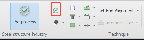
(1) Click Auto Technique and enable the required technique options.
(2) Import the parts and review the automatically added techniques.
※Notice: If parts have already been imported before enabling Auto Technique, only parts imported after activation will be applied the added techniques. Previously imported parts will not be applied the techniques automatically.
Ⅲ. Additional Notes
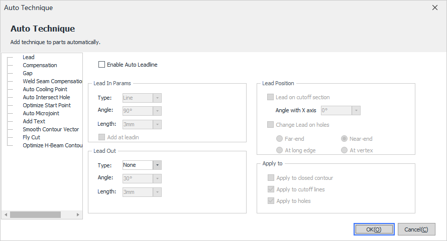
(1) Lead: Lead on the Auto Technique page refers to standard Lead Line only. For more descriptions, please refer to Lead Line tutorial.
(2) Compensation: Compensation on the Auto Technique page refers to standard kerf compensation. For more descriptions, please refer to Compensation tutorial.
-
-
- For fixed height compensation, please refer to the Kerf Compensation (fixed height) tutorial.
-
(3) Gap: For more descriptions, please refer to Gap tutorial.
(4) Weld Seam Compensation: For more descriptions, please refer to Weld Seam Compensation tutorial.
(5) Auto Cooling Point: For more descriptions, please refer to Cooling Point tutorial.
(6) Auto Intersect Hole: For more descriptions, please refer to Intersect Hole tutorial.
(7) Add Text: For more descriptions, please refer to Add Texttutorial.
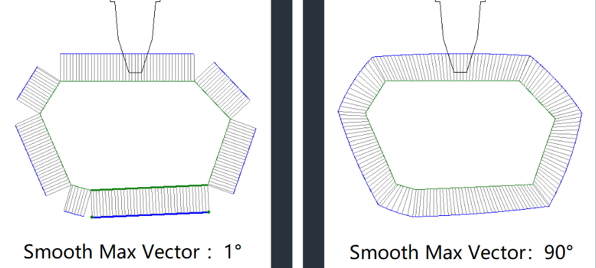
(8) Smooth Contour Vector: Smooth contour vector currently has no tutorial link. This function is mainly used to smooth sharply changed vector.
Max Smooth Angle: In cases where a toolpath on a special-shaped profile has a sudden vector change at a corner, this parameter defines the maximum allowable transition angle.
The configurable range is between 0.1° and 90°.
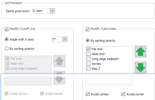
(9) Optimize Start Point:
(10) Fly Cut: For more descriptions, please refer to Fly Cut tutorial.
(11) Optimize H-Beam contour vector: Optimize H-Beam contour vector applies to non-bevel toolpaths using the chc cutting head model. For more descriptions, please refer to Edit Normal Vector of Contours tutorial.
-
-
- For bevel toolpaths, please refer to Collision-Avoid tutorial.
-
Ⅰ. Overview
If you are already familiar with certain technique configurations in TubesT, or the fixed technique parameters are used in your production, the Auto Technique feature can be enabled before importing parts. Once configured, the software will automatically add techniques to each part during import, eliminating the need for manual configuration afterward. Check the added techniques after import.
Ⅱ. Instructions
(1) Click Auto Technique and enable the required technique options.
(2) Import the parts and review the automatically added techniques.
※Notice: If parts have already been imported before enabling Auto Technique, only parts imported after activation will be applied the added techniques. Previously imported parts will not be applied the techniques automatically.
Ⅲ. Additional Notes
(1) Lead: Lead on the Auto Technique page refers to standard Lead Line only. For more descriptions, please refer to Lead Line tutorial.
(2) Compensation: Compensation on the Auto Technique page refers to standard kerf compensation. For more descriptions, please refer to Compensation tutorial.
-
-
- For fixed height compensation, please refer to the Kerf Compensation (fixed height) tutorial.
-
(3) Gap: For more descriptions, please refer to Gap tutorial.
(4) Weld Seam Compensation: For more descriptions, please refer to Weld Seam Compensation tutorial.
(5) Auto Cooling Point: For more descriptions, please refer to Cooling Point tutorial.
(6) Auto Intersect Hole: For more descriptions, please refer to Intersect Hole tutorial.
(7) Add Text: For more descriptions, please refer to Add Texttutorial.
(8) Smooth Contour Vector: Smooth contour vector currently has no tutorial link. This function is mainly used to smooth sharply changed vector.
Max Smooth Angle: In cases where a toolpath on a special-shaped profile has a sudden vector change at a corner, this parameter defines the maximum allowable transition angle.
The configurable range is between 0.1° and 90°.
(9) Optimize Start Point:
(10) Fly Cut: For more descriptions, please refer to Fly Cut tutorial.
(11) Optimize H-Beam contour vector: Optimize H-Beam contour vector applies to non-bevel toolpaths using the chc cutting head model. For more descriptions, please refer to Edit Normal Vector of Contours tutorial.
-
-
- For bevel toolpaths, please refer to Collision-Avoid tutorial.
-

