

-
Products
Overview Products

-
2D Cutting
-
Tube Cutting
-
3D Cutting
-
Intelligent Welding
-
Intelligent Cutting Head
-
Industrial Automation
-
Industrial Software
-
Combination
-
Combination
BOCHU New Product -
Combination
BOCHU New Product -
Controller
BOCHU New Product -
2D Cutting Head
Tube Cutting Head
3D Cutting Head
Consumables
BOCHU New Product -
Servo
BOCHU New Product -
Industrial 4.0
-
- Support
- About
- Online Store


- Software Download
- Manual
- Video
- Tutorial
Introduction
In the steel structure industry, Scallop in H-beams and flange bevel are highly common.
For such parts, users can leverage the function to generate cutting path. <Optimize H-beam web toolpath> automatically and batch-modifies cutting path (e.g., Y-bevel or arc transitions), significantly reducing manual cutting path adjustments, improving drafting efficiency, and lowering labor costs.
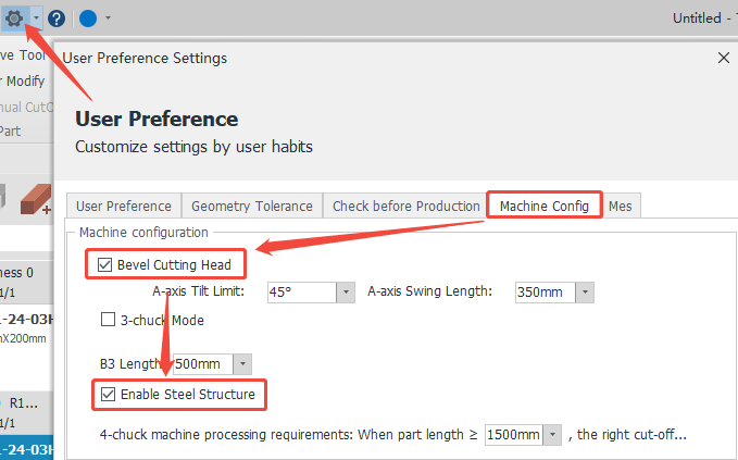
*You need to have the “Steel Framing Feature Pack”. Then, please check “Bevel Cutting Head” and “Enable Steel Structure” in <Machine Config> in <User Parameter Configuration>.
**If TubesT-H, it is enabled by default and does not need to be checked.
How to use
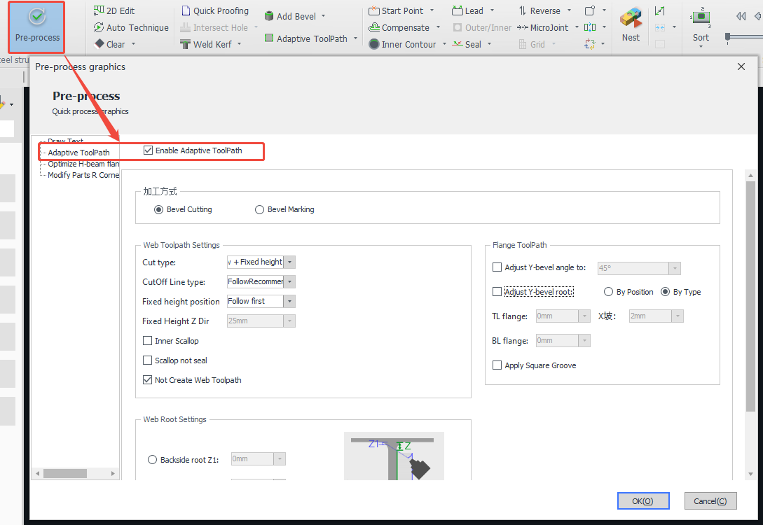
1、Before importing parts:<Pre-process>-<Enable Adaptive Toolpath>,recommended parameters are as follows:
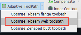
2、After importing parts:<Adaptive Toolpath>-<Optimize H-beam web toolpath>.
Parameter Meaning
1、Cutting method: Bevel cutting, Bevel marking
1) <Bevel cutting> generates a bevel cutting path in conjunction with the actual cutting path.
2) <Bevel marking> automatically replaces the machining layer of the bevel cutting trace line with the marking layer in <Layer Configuration>.
2、Web Toolpath Settings
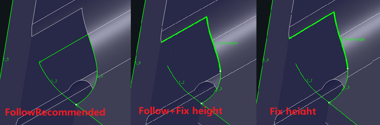
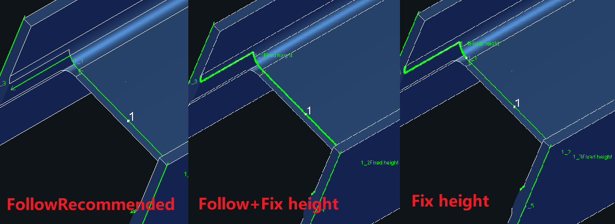
1)Scallop Cut type: FollowRecommened, Fix height, FollowRecommened+Fix height
You need to tick the box for fixed height, and set the fixed height in Tubepro or Facut+H if a fixed height is required. When cutting at a fixed height, the nozzle is usually higher than the flange plate.
2)Cutoff Line type:FollowRecommened, Fix height, FollowRecommened+Fix height
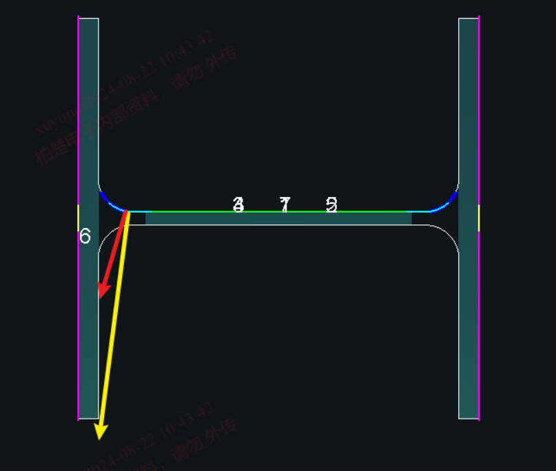
3)Fixed height position:Used to adjust the position of the split node between the fixed height and the follow knife path.
(This strategy selection can only be adjusted if ‘FollowRecommened + Fix height’ is selected for the over-welded hole cutting method or the cut-off line cutting method.)
Follow first: The red is the laser beam. The node splitting principle is to use follow cuts whenever possible (although it may appear to bruise the flange, it can actually be avoided by the process).
Fix Height first: The yellow is the laser beam that shoots right over the edge of the flange. Theoretically it will not cut the airfoil and requires less craftsmanship.
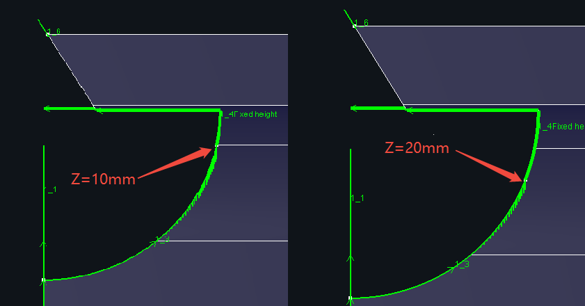
4)Fix Height Z dir:Customise the position of the split node
5 )Inner Scallop:When cutting down the bevel, the bevel toolpath has the potential to bruise the part.
If you cut the inner over-welded hole first (to give the wing bevel cutter path a slag discharge), then cut the flange bevel (at this point, even if you bruise the part, it's the scrap that gets bruised), and then finally cut the complete over-welded hole in the outer ring.
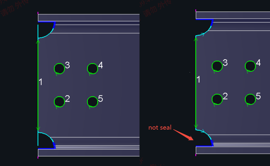
6)Scallop not seal
Previously, a cutting path for the over-solder hole would be added to facilitate the dropout (Figure 1 below). Starting from version 2025V1, the over-solder hole is supported without sealing (Figure 2 below)
7)Not Create Web Toolpath:Sometimes the web comes with a tiny degree bevel that doesn't really need to be cut.
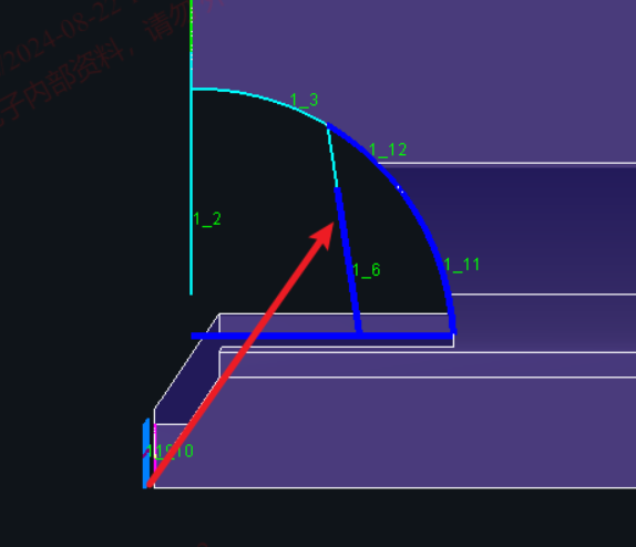
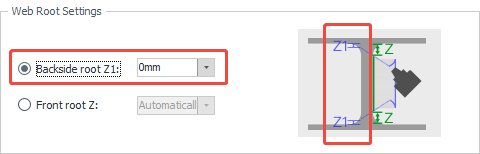
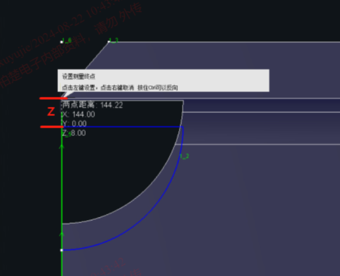
3、Web Root Settings
1)Backside Z1:When checked, the <Front Root Z> parameter setting is greyed out. The set backside rooting distance is the position shown in Z1 in the figure below.
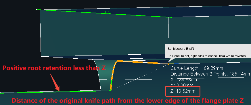
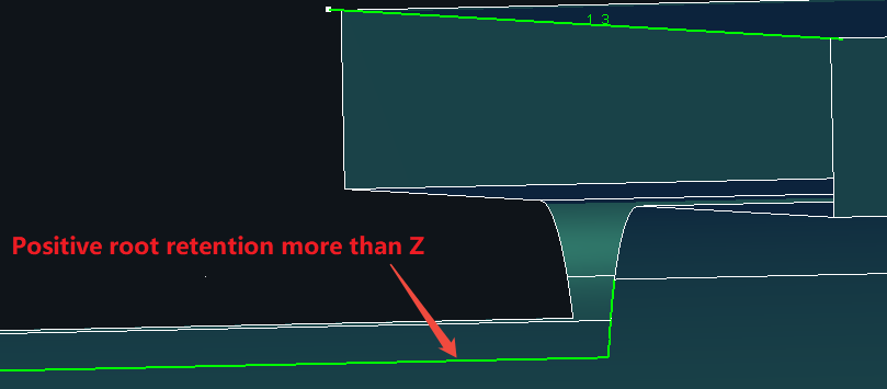
2)Front root Z:When checked, the <Backside Root Z1> parameter setting will be greyed out. The set distance of the front side root stay is the position shown in the following figure Z.It is the distance between the over-welded hole near the wing plate knife path and the lower edge of the wing plate. The effect after application is shown in the figure below.
Once the parameters are set, the toolpath is also affected by the position of the original model:
① The setup of root position, between the model position and the inside of the flange panel, the cutter path is generated at the model position.
② The setup of root position, which is not between the model position and the inner side of the flange, and the cutter path generation is going by the distance of the lower edge of the flange.
4、Flange ToolPath
* For parts that require bevelled cuts, it is necessary to identify the bevel first. Method of identifying the bevel:
① check <Bevel> in <Add from file interface> and then import the part.
② click <Generate Bevel> in the TubeDraw for the parts drawn by the TubesT.
1) Adjust Y-slope Angle: When checked, the bevel toolpath will be generated according to the set angle.
2) Adjust Y-slope stay root: After checking, you can set the Y-slope stay root according to the actual need. When leave root is set to 0, it is V slope.
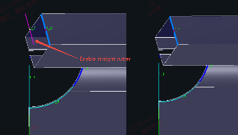
3) Enable straight cutter for V slope: When cutting V slope, if you don't want to cut straight cutter, you can uncheck the box. The specific difference is shown in the figure below.
Introduction
In the steel structure industry, Scallop in H-beams and flange bevel are highly common.
For such parts, users can leverage the function to generate cutting path. <Optimize H-beam web toolpath> automatically and batch-modifies cutting path (e.g., Y-bevel or arc transitions), significantly reducing manual cutting path adjustments, improving drafting efficiency, and lowering labor costs.
*You need to have the “Steel Framing Feature Pack”. Then, please check “Bevel Cutting Head” and “Enable Steel Structure” in <Machine Config> in <User Parameter Configuration>.
**If TubesT-H, it is enabled by default and does not need to be checked.
How to use
1、Before importing parts:<Pre-process>-<Enable Adaptive Toolpath>,recommended parameters are as follows:
2、After importing parts:<Adaptive Toolpath>-<Optimize H-beam web toolpath>.
Parameter Meaning
1、Cutting method: Bevel cutting, Bevel marking
1) <Bevel cutting> generates a bevel cutting path in conjunction with the actual cutting path.
2) <Bevel marking> automatically replaces the machining layer of the bevel cutting trace line with the marking layer in <Layer Configuration>.
2、Web Toolpath Settings
1)Scallop Cut type: FollowRecommened, Fix height, FollowRecommened+Fix height
You need to tick the box for fixed height, and set the fixed height in Tubepro or Facut+H if a fixed height is required. When cutting at a fixed height, the nozzle is usually higher than the flange plate.
2)Cutoff Line type:FollowRecommened, Fix height, FollowRecommened+Fix height
3)Fixed height position:Used to adjust the position of the split node between the fixed height and the follow knife path.
(This strategy selection can only be adjusted if ‘FollowRecommened + Fix height’ is selected for the over-welded hole cutting method or the cut-off line cutting method.)
Follow first: The red is the laser beam. The node splitting principle is to use follow cuts whenever possible (although it may appear to bruise the flange, it can actually be avoided by the process).
Fix Height first: The yellow is the laser beam that shoots right over the edge of the flange. Theoretically it will not cut the airfoil and requires less craftsmanship.
4)Fix Height Z dir:Customise the position of the split node
5 )Inner Scallop:When cutting down the bevel, the bevel toolpath has the potential to bruise the part.
If you cut the inner over-welded hole first (to give the wing bevel cutter path a slag discharge), then cut the flange bevel (at this point, even if you bruise the part, it's the scrap that gets bruised), and then finally cut the complete over-welded hole in the outer ring.
6)Scallop not seal
Previously, a cutting path for the over-solder hole would be added to facilitate the dropout (Figure 1 below). Starting from version 2025V1, the over-solder hole is supported without sealing (Figure 2 below)
7)Not Create Web Toolpath:Sometimes the web comes with a tiny degree bevel that doesn't really need to be cut.
3、Web Root Settings
1)Backside Z1:When checked, the <Front Root Z> parameter setting is greyed out. The set backside rooting distance is the position shown in Z1 in the figure below.
2)Front root Z:When checked, the <Backside Root Z1> parameter setting will be greyed out. The set distance of the front side root stay is the position shown in the following figure Z.It is the distance between the over-welded hole near the wing plate knife path and the lower edge of the wing plate. The effect after application is shown in the figure below.
Once the parameters are set, the toolpath is also affected by the position of the original model:
① The setup of root position, between the model position and the inside of the flange panel, the cutter path is generated at the model position.
② The setup of root position, which is not between the model position and the inner side of the flange, and the cutter path generation is going by the distance of the lower edge of the flange.
4、Flange ToolPath
* For parts that require bevelled cuts, it is necessary to identify the bevel first. Method of identifying the bevel:
① check <Bevel> in <Add from file interface> and then import the part.
② click <Generate Bevel> in the TubeDraw for the parts drawn by the TubesT.
1) Adjust Y-slope Angle: When checked, the bevel toolpath will be generated according to the set angle.
2) Adjust Y-slope stay root: After checking, you can set the Y-slope stay root according to the actual need. When leave root is set to 0, it is V slope.
3) Enable straight cutter for V slope: When cutting V slope, if you don't want to cut straight cutter, you can uncheck the box. The specific difference is shown in the figure below.

