

-
Products
Overview Products

-
2D Cutting
-
Tube Cutting
-
3D Cutting
-
Intelligent Welding
-
Intelligent Cutting Head
-
Industrial Automation
-
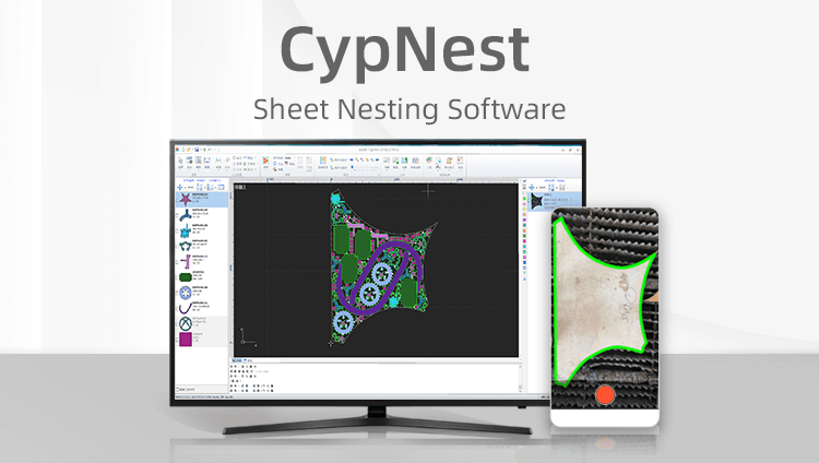
Industrial Software
-
Combination
-
Combination
BOCHU New Product -
Combination
BOCHU New Product -
Controller
BOCHU New Product -
2D Cutting Head
Tube Cutting Head
3D Cutting Head
Consumables
BOCHU New Product -
Servo
BOCHU New Product -
Industrial 4.0
-
- Support
- About
- Online Store


- Software Download
- Manual
- Tutorial
- CloudNest
You may encounter a situation where the Co-Edge option is enabled but no co-edges are actually applied during nest. How to resolve this issue?
First, enable Highlight Co-Edged to verify if parts are nested with co-edges. If co-edges are applied, they will be displayed in yellow.

1. Verify Correct Parameters. Recommended parameters are as follows:

2. Check Part Gap Settings
Set the part gap according to actual requirements, do not set it to 0.1.

3. Check Drawing Errors of Parts
Measure the edges of parts and check the length values in the X and Y directions in the log panel.
For example, the part below has a slight offset in the X direction, meaning its edge is not vertical — this will lead to co-edge nest failure.

Two solutions are available for this issue:
(1) Return to the CAD software to modify the part drawing.
(2) If high precision is not required, use the Post-processing- Co-Edge Precision Process to achieve the co-edge effect.
4. Check if the current version is the latest version.
It is recommended to upgrade to the latest official release. You can download the latest software version from the official website.
5. Further Technical Support
If the common edge issue persists after completing the above operation steps, save the nest file and send it to the official communication group for technical staff to diagnose and resolve.

You may encounter a situation where the Co-Edge option is enabled but no co-edges are actually applied during nest. How to resolve this issue?
First, enable Highlight Co-Edged to verify if parts are nested with co-edges. If co-edges are applied, they will be displayed in yellow.
1. Verify Correct Parameters. Recommended parameters are as follows:
2. Check Part Gap Settings
Set the part gap according to actual requirements, do not set it to 0.1.
3. Check Drawing Errors of Parts
Measure the edges of parts and check the length values in the X and Y directions in the log panel.
For example, the part below has a slight offset in the X direction, meaning its edge is not vertical — this will lead to co-edge nest failure.
Two solutions are available for this issue:
(1) Return to the CAD software to modify the part drawing.
(2) If high precision is not required, use the Post-processing- Co-Edge Precision Process to achieve the co-edge effect.
4. Check if the current version is the latest version.
It is recommended to upgrade to the latest official release. You can download the latest software version from the official website.
5. Further Technical Support
If the common edge issue persists after completing the above operation steps, save the nest file and send it to the official communication group for technical staff to diagnose and resolve.

