

-
Products
Overview Products

-
2D Cutting
-
Tube Cutting
-
3D Cutting
-
Intelligent Welding
-
Intelligent Cutting Head
-
Industrial Automation
-
Industrial Software
-
Combination
-
Combination
BOCHU New Product -
Combination
BOCHU New Product -
Controller
BOCHU New Product -
2D Cutting Head
Tube Cutting Head
3D Cutting Head
Consumables
BOCHU New Product -
Servo
BOCHU New Product -
Industrial 4.0
-
- Support
- About
- Online Store


- Software Download
- Manual
- Video
- Tutorial
Ⅰ. Overview
To improve material utilization and machining efficiency, the Auto Nest function helps you arrange processed parts onto the tube in an optimized layout.

Ⅱ. UI Changes
Since TubesT V1.59, the Auto Nest interface has been optimized. The following shows the differences before and after the update:
 TubesT V1.55 and earlier
 TubesT V1.55 and later
Ⅲ. Operation and Parameter Description
1.How much tube length is actually available for nesting?
The usable nesting length is determined by three parameters: tube length, dead zone, and front margin.
Nesting Length = Tube Length – Dead Zone – Front Margin
-
-
-
-
Tube Length: Total length of the tube.
-
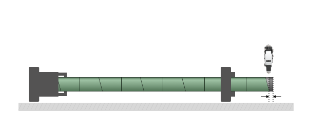
Dead Zone: The distance from the tube tail held by the jaw to the cutting head centerline when the front chuck moves to its closest position to the mid chuck. It is also called the uncut tail length.
-
-
-
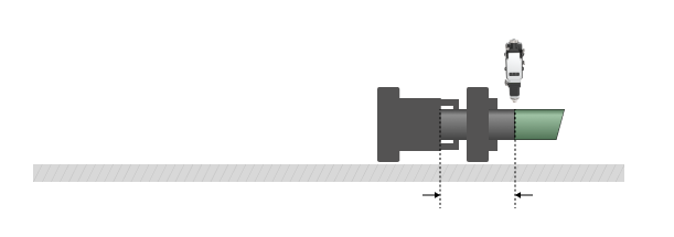
For a two-chuck tube cutting machine, if the front chuck reaches its mechanical limit and 230 mm of tail material remains uncut, you can set the Dead Zone to 230 mm.
For a three-chuck tube cutting machine with material handling or dodge functions that enable zero tail cutting, you can set the Dead Zone to 0.
-
-
-
- Front Margin: The reserved distance between the tube head and the first part.
-
-
In TubesT, this parameter means reserving a non-nestable length at the tube head. It only affects the reserved length and does not visually render on the tube head in the main interface. In actual production, it should be used together with Quick Align Tube Head in TubePro.
2. How to enable co-edge cutting to improve efficiency?
-
-
- Identical Co-edge: When two parts share a common edge, the cut-off line fully overlaps.
-
-
-
- 3-Cut Co-edge: Used for beveled end-face co-edge cutting when Weld Seam Compensation is applied.
-
-
-
- Island Co-edge: Waste material exists along the shared cutoff line between two parts. For details, refer to TubesT – Island Co-edge.
-
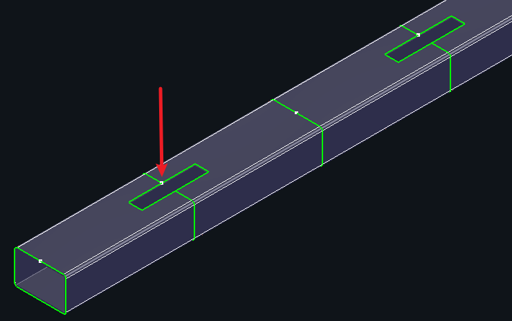
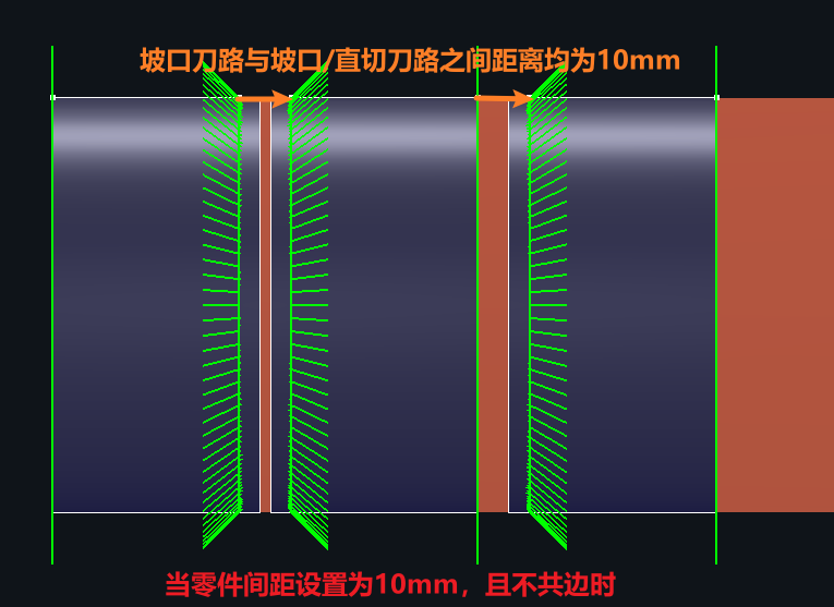
3. When co-edge is not applied, how is spacing controlled?
Through the Parts gap parameter.
It means the minimum toolpath distance maintained between parts when co-edge is not used.
When nesting beveled parts without co-edge, please adjust the parts gap properly to avoid vector overlap or collision that may damage adjacent parts.
4. What other nesting parameters affect the results?
-
-
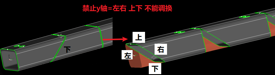
- Disable Y Rotate: Prevents rotation of parts around the Y-axis during nesting.
-
-
-
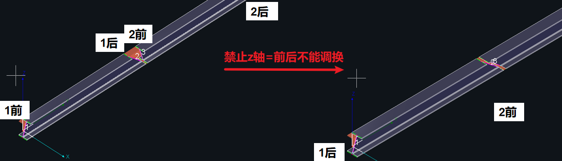
- Disable Z Rotate: Prevents rotation of parts around the Z-axis during nesting. In TubesT-H, this option is labeled Disable X Rotate.
-
-
-
- Circular tube free rotation: Allows round tube parts to rotate freely around the Y-axis for better material utilization. This option was removed after TubesT V7.1.57 and is now enabled by default.
-
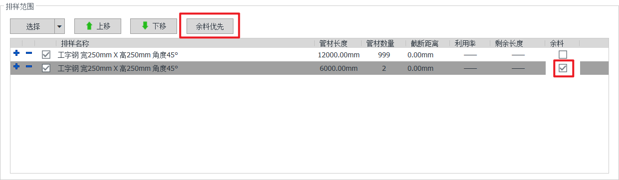
5. How to use remnant materials?
If remnant tubes are available and you want them to be nested before full-length tubes:
Tick Remnant and click Remnant First to prioritize it.
As is shown in the figure below, TubesT will automatically prioritize nesting two 6,000 mm remnants before nesting the 12,000 mm tube.
6. What special nesting strategies are available?
Note: The following functions require enabling Utilization First before use.
-
-
- Smooth Speed: When nesting a large number of parts and faster nesting is required, this option balances utilization and speed. This function has been removed after TubesT 25V2 and the default strategy is Best Result.
- Best Result: Maximizes material utilization. Nesting time may be longer.
- Extreme Speed: Fastest calculation speed. Material utilization may decrease for complex parts.
- Smooth Speed: When nesting a large number of parts and faster nesting is required, this option balances utilization and speed. This function has been removed after TubesT 25V2 and the default strategy is Best Result.
-
-
-
- Straight cut position: Ensures that the front/rear-end cut in the nesting result is a straight cut. This can improve utilization and reduce toolpaths.
-
See TubesT – Front/Rear-end First for details.
-
-
- Nest in Tail-Short part/Long part: For machines supporting dodge or material handling that enable short or zero tail cutting, you may require specific parts to be placed at the end of the tube.
-
Take Long part as an example. You need set a length threshold to define long parts. After generating an optimized nesting result, TubesT will automatically move long parts to the end.
Different machines have different nesting requirements: some require long parts at the tail, others require short parts at the tail.
For details, see:
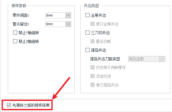
7. Other parameters
-
-
- Clear nest results first
-
-
-
-
-
Enable: Clears previous nesting results before re-nesting.
-
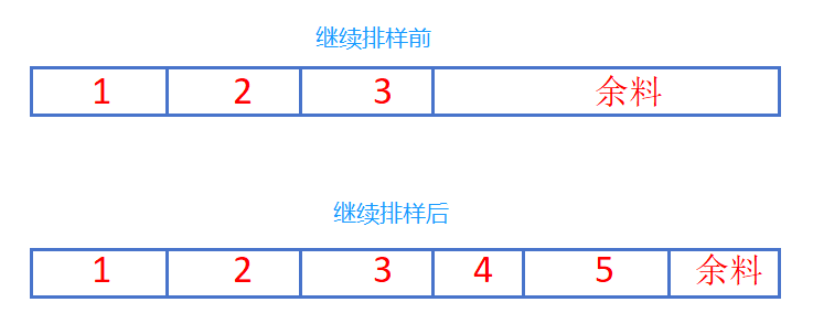
Disable: Continues nesting based on the existing results.
-
-
-
The meaning of continuing nesting can be illustrated in the following figure.
Ⅳ. FAQs
1.How to manually adjust nesting results if unsatisfied?
2.How to stop the nesting progress if the nesting time is too long?
From version 7.1.39, a progress bar of auto nesting is available.
If you terminate the progress during nesting, TubesT will exit the algorithm within 2 minutes and retain the current optimal result.
Do not forcibly terminate the progress within 2 minutes.
To manually stop and keep the result immediately, please click Use current result.

3.Manual Nest
In most cases, Auto Nest can meet most of your nesting requirements. If it cannot satisfy specific production needs, you can use the Manual Nest function instead.
For details, refer to TubesT – Manual Nest.
4.Bevel Nesting
In particular, please note the following for bevel nesting.
(1)Bevel Co-edge
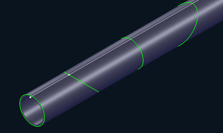
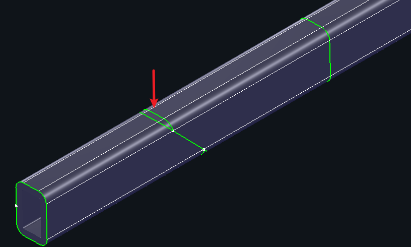
When Bevel Identical Co-edge is enabled, title bevels on square tube, circular tube, angle section, channel section, and I-beam section support co-edge.
Note: Bevels added using a straight cut toolpath do not support co-edge.

When Bevel Island Co-edge is enabled, the following joint types in Loop Nesting support co-edge, with single part toolpath:
-
-
-
-
- Straight Cut: With or without retaining the V-bevel from the straight cut.
- Center Z Shape: With or without retaining the V-bevel from the straight cut.
- Z Shape: V-bevel.
-
-
-
Note: Loop Nesting is an exclusive feature of the Steel Structure Package. If the nesting interface does not show the Loop Nesting option, you need to claim or enable the permission first.

(2)Parts Gap for Bevel Parts
Currently, the parts gap is calculated based on toolpaths only and does not account for the laser beam influence zone.
For beveled parts, set the parts gap to greater than:
Thickness × 2 + 6 mm
Otherwise, bevel cutting quality may be affected.
Ⅰ. Overview
To improve material utilization and machining efficiency, the Auto Nest function helps you arrange processed parts onto the tube in an optimized layout.
Ⅱ. UI Changes
Since TubesT V1.59, the Auto Nest interface has been optimized. The following shows the differences before and after the update:
TubesT V1.55 and earlier
TubesT V1.55 and later
Ⅲ. Operation and Parameter Description
1.How much tube length is actually available for nesting?
The usable nesting length is determined by three parameters: tube length, dead zone, and front margin.
Nesting Length = Tube Length – Dead Zone – Front Margin
-
-
-
-
Tube Length: Total length of the tube.
-
Dead Zone: The distance from the tube tail held by the jaw to the cutting head centerline when the front chuck moves to its closest position to the mid chuck. It is also called the uncut tail length.
-
-
-
For a two-chuck tube cutting machine, if the front chuck reaches its mechanical limit and 230 mm of tail material remains uncut, you can set the Dead Zone to 230 mm.
For a three-chuck tube cutting machine with material handling or dodge functions that enable zero tail cutting, you can set the Dead Zone to 0.
-
-
-
- Front Margin: The reserved distance between the tube head and the first part.
-
-
In TubesT, this parameter means reserving a non-nestable length at the tube head. It only affects the reserved length and does not visually render on the tube head in the main interface. In actual production, it should be used together with Quick Align Tube Head in TubePro.
2. How to enable co-edge cutting to improve efficiency?
-
-
- Identical Co-edge: When two parts share a common edge, the cut-off line fully overlaps.
-
-
-
- 3-Cut Co-edge: Used for beveled end-face co-edge cutting when Weld Seam Compensation is applied.
-
-
-
- Island Co-edge: Waste material exists along the shared cutoff line between two parts. For details, refer to TubesT – Island Co-edge.
-
3. When co-edge is not applied, how is spacing controlled?
Through the Parts gap parameter.
It means the minimum toolpath distance maintained between parts when co-edge is not used.
When nesting beveled parts without co-edge, please adjust the parts gap properly to avoid vector overlap or collision that may damage adjacent parts.
4. What other nesting parameters affect the results?
-
-
- Disable Y Rotate: Prevents rotation of parts around the Y-axis during nesting.
-
-
-
- Disable Z Rotate: Prevents rotation of parts around the Z-axis during nesting. In TubesT-H, this option is labeled Disable X Rotate.
-
-
-
- Circular tube free rotation: Allows round tube parts to rotate freely around the Y-axis for better material utilization. This option was removed after TubesT V7.1.57 and is now enabled by default.
-
5. How to use remnant materials?
If remnant tubes are available and you want them to be nested before full-length tubes:
Tick Remnant and click Remnant First to prioritize it.
As is shown in the figure below, TubesT will automatically prioritize nesting two 6,000 mm remnants before nesting the 12,000 mm tube.
6. What special nesting strategies are available?
Note: The following functions require enabling Utilization First before use.
-
-
- Smooth Speed: When nesting a large number of parts and faster nesting is required, this option balances utilization and speed. This function has been removed after TubesT 25V2 and the default strategy is Best Result.
- Best Result: Maximizes material utilization. Nesting time may be longer.
- Extreme Speed: Fastest calculation speed. Material utilization may decrease for complex parts.
- Smooth Speed: When nesting a large number of parts and faster nesting is required, this option balances utilization and speed. This function has been removed after TubesT 25V2 and the default strategy is Best Result.
-
-
-
- Straight cut position: Ensures that the front/rear-end cut in the nesting result is a straight cut. This can improve utilization and reduce toolpaths.
-
See TubesT – Front/Rear-end First for details.
-
-
- Nest in Tail-Short part/Long part: For machines supporting dodge or material handling that enable short or zero tail cutting, you may require specific parts to be placed at the end of the tube.
-
Take Long part as an example. You need set a length threshold to define long parts. After generating an optimized nesting result, TubesT will automatically move long parts to the end.
Different machines have different nesting requirements: some require long parts at the tail, others require short parts at the tail.
For details, see:
7. Other parameters
-
-
- Clear nest results first
-
-
-
-
-
Enable: Clears previous nesting results before re-nesting.
-
Disable: Continues nesting based on the existing results.
-
-
-
The meaning of continuing nesting can be illustrated in the following figure.
Ⅳ. FAQs
1.How to manually adjust nesting results if unsatisfied?
2.How to stop the nesting progress if the nesting time is too long?
From version 7.1.39, a progress bar of auto nesting is available.
If you terminate the progress during nesting, TubesT will exit the algorithm within 2 minutes and retain the current optimal result.
Do not forcibly terminate the progress within 2 minutes.
To manually stop and keep the result immediately, please click Use current result.
3.Manual Nest
In most cases, Auto Nest can meet most of your nesting requirements. If it cannot satisfy specific production needs, you can use the Manual Nest function instead.
For details, refer to TubesT – Manual Nest.
4.Bevel Nesting
In particular, please note the following for bevel nesting.
(1)Bevel Co-edge
When Bevel Identical Co-edge is enabled, title bevels on square tube, circular tube, angle section, channel section, and I-beam section support co-edge.
Note: Bevels added using a straight cut toolpath do not support co-edge.
When Bevel Island Co-edge is enabled, the following joint types in Loop Nesting support co-edge, with single part toolpath:
-
-
-
-
- Straight Cut: With or without retaining the V-bevel from the straight cut.
- Center Z Shape: With or without retaining the V-bevel from the straight cut.
- Z Shape: V-bevel.
-
-
-
Note: Loop Nesting is an exclusive feature of the Steel Structure Package. If the nesting interface does not show the Loop Nesting option, you need to claim or enable the permission first.
(2)Parts Gap for Bevel Parts
Currently, the parts gap is calculated based on toolpaths only and does not account for the laser beam influence zone.
For beveled parts, set the parts gap to greater than:
Thickness × 2 + 6 mm
Otherwise, bevel cutting quality may be affected.

