

-
Products
Overview Products

-
2D Cutting
-
Tube Cutting
-
3D Cutting
-
Intelligent Welding
-
Intelligent Cutting Head
-
Industrial Automation
-
Industrial Software
-
Combination
-
Combination
BOCHU New Product -
Combination
BOCHU New Product -
Controller
BOCHU New Product -
2D Cutting Head
Tube Cutting Head
3D Cutting Head
Consumables
BOCHU New Product -
Servo
BOCHU New Product -
Industrial 4.0
-
- Support
- About
- Online Store


- Software Download
- Manual
- Video
- Tutorial
Ⅰ. Overview
FlyCut is a processing method used when holes on tubes are regular shapes (e.g., circles, rectangles) arranged in repetitive layouts.
This method significantly enhances efficiency by linking same-orientation line segments into continuous motion sequences.
Ⅱ. Function Guide
1. Version Compatibility
-
- For TubePro prior to V7.19.160.5
- Exclusively available on FSCUT5000A and FSCUT5000B systems.
- FSCUT3000S systems are incompatible—attempting to apply FlyCut may cause unintended continuous cutting.
- For TubePro prior to V7.19.160.5
-
- For TubePro V7.19.160.5 or higher
- From non-bus FSCUT3000S systems, FlyCut is accessible.
- For TubePro V7.19.160.5 or higher
-
- For TubesT V7.1.59.1 or higher
- One-Path Flycut is introduced.
- Linear FlyCut supports sorting by X axis or Y axis direction.
- For TubesT V7.1.59.1 or higher
2. Function Description
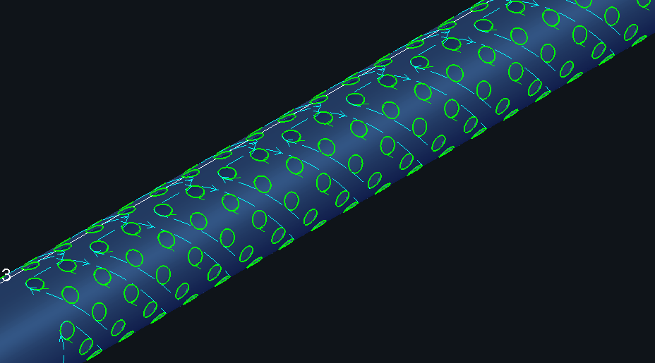
(1)Circular FlyCut: Used for regularly arranged circular holes across all tubular profiles (round/rectangular).
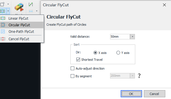
Valid distance: FlyCut paths can only be generated when the starting-point distance between circular holes is less than the set value. It is recommended to configure this parameter slightly larger than the actual hole spacing.
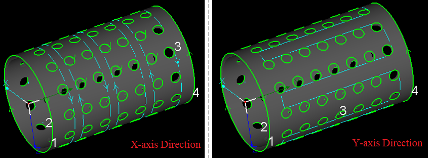
Sort direction: Refers to the direction for FlyCut paths, determining the hole-cutting sequence.
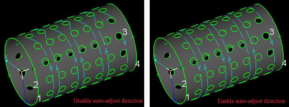
Auto-adjust direction: Helps to resolve the chaotic FlyCut paths caused by different starting positions or cutting directions across circular holes. Therefore, it is advised to enable this function unless specific process requirements are required. When enabled, the software automatically adjusts the cutting direction of circular holes based on the FlyCut paths.
-
-
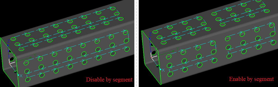
- By segment: For long parts, it is recommended to enable this function to eliminate excessive Y-axis motions over extended travel distances.
-
From TubesT V7.1.45.1 or higher, the software now supports FlyCut for staggered geometric graphics.
(2)Linear FlyCut: Designed for regularly arranged sharp-cornered rectangular or diamond-shaped holes, and applicable to tubular profiles (round and rectangular).
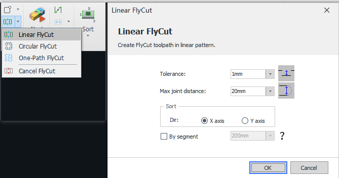
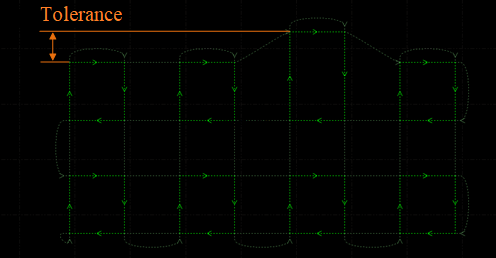
Tolerance: During FlyCut path generation for co-linear segments, any linear segment within the set value will be consolidated into a continuous FlyCut path. Default is 20 mm.
-
-
- Max joint distance: The software makes smooth path connections below the set value when transitioning between cutting rows. It is recommended to retain the default setting.
-
-
-
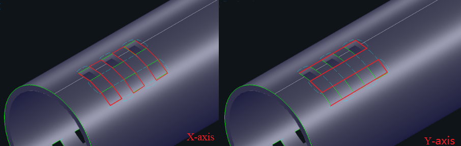
- Sort: The default FlyCut sequence prioritizes X-axis direction, followed by Y-axis direction. During tube clamping and positioning operations, residual uncut sections may deform within the chuck assembly, or unremoved debris may dislodge into critical chuck mechanisms. In such scenarios, direction adjustment is permitted to mitigate these risks.
-
-
-
- By segment: For long parts, it is recommended to enable this function to eliminate excessive Y-axis motions over extended travel distances.
-
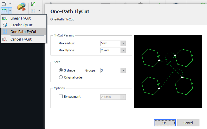
(3)One-Path FlyCut: Supported in TubesT V7.1.59.1 or higher. This function enables continuous processing of all geometric graphics (excluding characters), typically applicable to obround slot arrays and rounded rectangular hole arrays.
-
-
- Max radius: The maximum radius applied during FlyCut path directional transitions (recommended default value: 3 mm)
-
-
-
- Max fly line: The maximum linear distance between two adjacent geometric graphics.
-
-
-
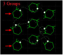
- S shape: In the nesting area, the cutting paths follow an S-like direction, shown in the figure below.
-
-
-
- Groups: Set the group quantity for path optimization when FlyCut paths follow an S shape.
-
-
-
- Original order: When enabled, the software maintains the original geometric order after generating FlyCut paths. Primarily used for specialized scenarios requiring strict adherence to internal contour processing sequences.
-
-
-
- By segment: For long parts, it is recommended to enable this function to eliminate excessive Y-axis motions over extended travel distances.
-
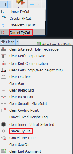
(4)Cancel FlyCut: To adjust parameters after FlyCut paths are generated, click target parts first, then click Cancel FlyCut to regenerate paths with updated parameters. Accessible in both the FlyCut and Clear dropdown menus.
Ⅲ. FAQS
- How to automatically apply FlyCut?
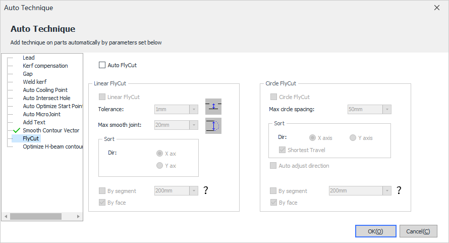
From TubesT V7.1.45.1, FlyCut is accessible in the Auto Technique interface. When enabled Auto FlyCut, the imported parts will automatically generate FlyCut paths.
- How to apply different techniques during FlyCut?
1. In TubesT, generate FlyCut paths to the target hole groups.
2. Select the groups, and assign distinct color-coded layers to different groups.
3. Set specific processing parameters for each layer in the laser cutting system.
- How to apply FlyCut to Intersect Holes?
First set target holes as Intersect Holes, then use FlyCut to generate paths.
-
-
- Processing effect of intersecting holes on round tube: during cutting of each row of holes, the B-axis remains stationary while the cutting head moves along the X-axis.
-
-
-
- Processing effect of common holes on round tube: during cutting of each row of holes, the X-axis remains stationary while the cutting head moves along the B-axis.
-
Ⅰ. Overview
FlyCut is a processing method used when holes on tubes are regular shapes (e.g., circles, rectangles) arranged in repetitive layouts.
This method significantly enhances efficiency by linking same-orientation line segments into continuous motion sequences.
Ⅱ. Function Guide
1. Version Compatibility
-
- For TubePro prior to V7.19.160.5
- Exclusively available on FSCUT5000A and FSCUT5000B systems.
- FSCUT3000S systems are incompatible—attempting to apply FlyCut may cause unintended continuous cutting.
- For TubePro prior to V7.19.160.5
-
- For TubePro V7.19.160.5 or higher
- From non-bus FSCUT3000S systems, FlyCut is accessible.
- For TubePro V7.19.160.5 or higher
-
- For TubesT V7.1.59.1 or higher
- One-Path Flycut is introduced.
- Linear FlyCut supports sorting by X axis or Y axis direction.
- For TubesT V7.1.59.1 or higher
2. Function Description
(1)Circular FlyCut: Used for regularly arranged circular holes across all tubular profiles (round/rectangular).
Valid distance: FlyCut paths can only be generated when the starting-point distance between circular holes is less than the set value. It is recommended to configure this parameter slightly larger than the actual hole spacing.
Sort direction: Refers to the direction for FlyCut paths, determining the hole-cutting sequence.
Auto-adjust direction: Helps to resolve the chaotic FlyCut paths caused by different starting positions or cutting directions across circular holes. Therefore, it is advised to enable this function unless specific process requirements are required. When enabled, the software automatically adjusts the cutting direction of circular holes based on the FlyCut paths.
-
-
- By segment: For long parts, it is recommended to enable this function to eliminate excessive Y-axis motions over extended travel distances.
-
From TubesT V7.1.45.1 or higher, the software now supports FlyCut for staggered geometric graphics.
(2)Linear FlyCut: Designed for regularly arranged sharp-cornered rectangular or diamond-shaped holes, and applicable to tubular profiles (round and rectangular).
Tolerance: During FlyCut path generation for co-linear segments, any linear segment within the set value will be consolidated into a continuous FlyCut path. Default is 20 mm.
-
-
- Max joint distance: The software makes smooth path connections below the set value when transitioning between cutting rows. It is recommended to retain the default setting.
-
-
-
- Sort: The default FlyCut sequence prioritizes X-axis direction, followed by Y-axis direction. During tube clamping and positioning operations, residual uncut sections may deform within the chuck assembly, or unremoved debris may dislodge into critical chuck mechanisms. In such scenarios, direction adjustment is permitted to mitigate these risks.
-
-
-
- By segment: For long parts, it is recommended to enable this function to eliminate excessive Y-axis motions over extended travel distances.
-
(3)One-Path FlyCut: Supported in TubesT V7.1.59.1 or higher. This function enables continuous processing of all geometric graphics (excluding characters), typically applicable to obround slot arrays and rounded rectangular hole arrays.
-
-
- Max radius: The maximum radius applied during FlyCut path directional transitions (recommended default value: 3 mm)
-
-
-
- Max fly line: The maximum linear distance between two adjacent geometric graphics.
-
-
-
- S shape: In the nesting area, the cutting paths follow an S-like direction, shown in the figure below.
-
-
-
- Groups: Set the group quantity for path optimization when FlyCut paths follow an S shape.
-
-
-
- Original order: When enabled, the software maintains the original geometric order after generating FlyCut paths. Primarily used for specialized scenarios requiring strict adherence to internal contour processing sequences.
-
-
-
- By segment: For long parts, it is recommended to enable this function to eliminate excessive Y-axis motions over extended travel distances.
-
(4)Cancel FlyCut: To adjust parameters after FlyCut paths are generated, click target parts first, then click Cancel FlyCut to regenerate paths with updated parameters. Accessible in both the FlyCut and Clear dropdown menus.
Ⅲ. FAQS
- How to automatically apply FlyCut?
From TubesT V7.1.45.1, FlyCut is accessible in the Auto Technique interface. When enabled Auto FlyCut, the imported parts will automatically generate FlyCut paths.
- How to apply different techniques during FlyCut?
1. In TubesT, generate FlyCut paths to the target hole groups.
2. Select the groups, and assign distinct color-coded layers to different groups.
3. Set specific processing parameters for each layer in the laser cutting system.
- How to apply FlyCut to Intersect Holes?
First set target holes as Intersect Holes, then use FlyCut to generate paths.
-
-
- Processing effect of intersecting holes on round tube: during cutting of each row of holes, the B-axis remains stationary while the cutting head moves along the X-axis.
-
-
-
- Processing effect of common holes on round tube: during cutting of each row of holes, the X-axis remains stationary while the cutting head moves along the B-axis.
-

