

-
Products
Overview Products

-
2D Cutting
-
Tube Cutting
-
3D Cutting
-
Intelligent Welding
-
Intelligent Cutting Head
-
Industrial Automation
-
Industrial Software
-
Combination
-
Combination
BOCHU New Product -
Combination
BOCHU New Product -
Controller
BOCHU New Product -
2D Cutting Head
Tube Cutting Head
3D Cutting Head
Consumables
BOCHU New Product -
Servo
BOCHU New Product -
Industrial 4.0
-
- Support
- About
- Online Store


- Software Download
- Manual
- Video
- Tutorial
What is geometric constraints?
The various shapes in a 2D sketch are interrelated and form geometric constraints, which are called geometric constraints.
For example, two lines being "perpendicular" or two circles being "equal" are considered geometric constraints. These constraints can be added to a 2D sketch using drawing tools, to ensure that the shapes in the sketch satisfy specific geometric relationships.
Geometric constraints are very important in CAD software, as they help designers to quickly create accurate and consistent sketches, and can automatically update the sketch shapes to ensure they always satisfy the specified geometric constraints. This improves design efficiency and accuracy, and reduces the likelihood of errors and repetitive work.
How to add geometric constraints in SmartDraw?
Below are three ways to add geometric constraints in SmartDraw.
1.Auto add constraints when drawing a geometry
When drawing a geometry, its geometric constraints will be automatically added based on shape capturing or drawing tool properties.
For example, when using the "Parallel Lines" command to draw parallel lines, the "Parallel" constraint relationship will be automatically generated.
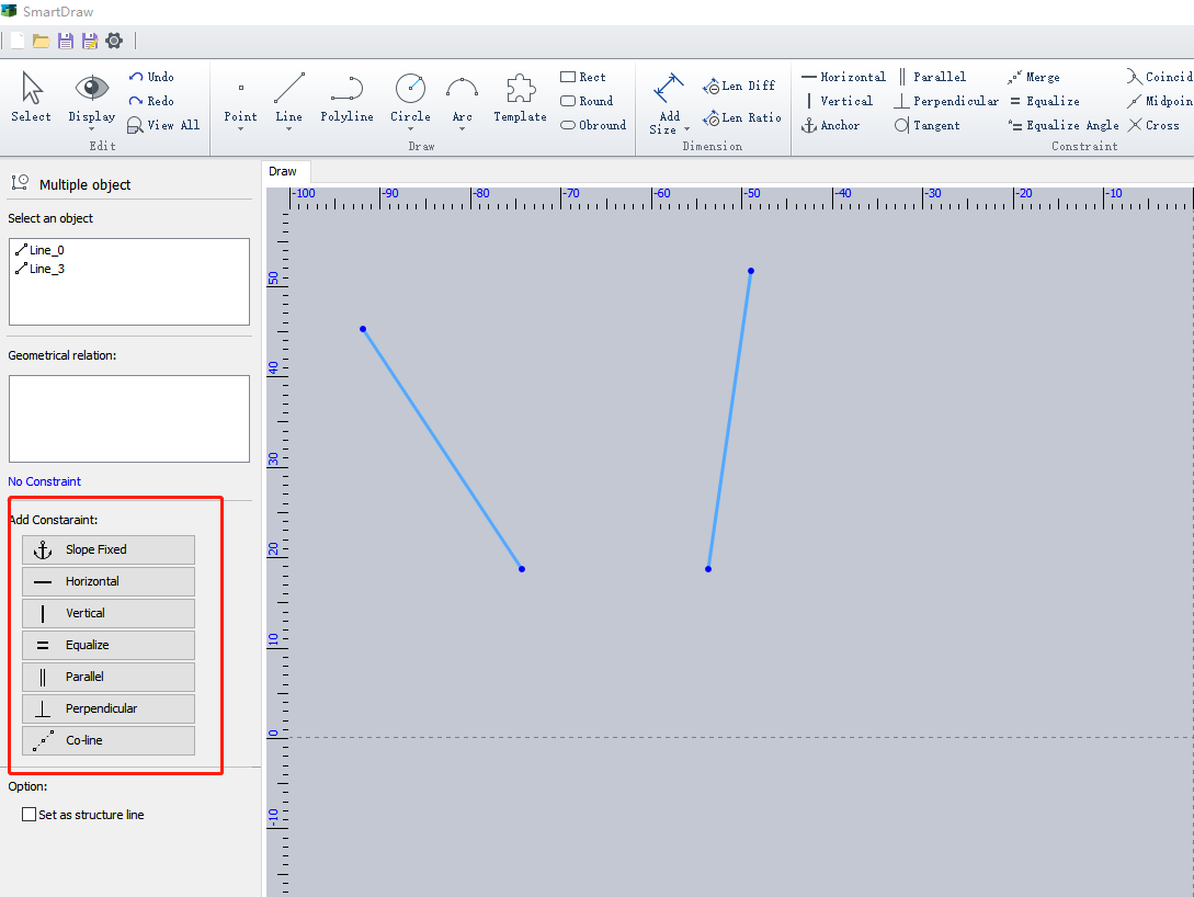
2.Add constraints after selecting a geometry
Select multiple graphics (hold Shift to select) first, and then set the constraints between graphics in the left information bar.
3.Click Constraints Then Select Geometry
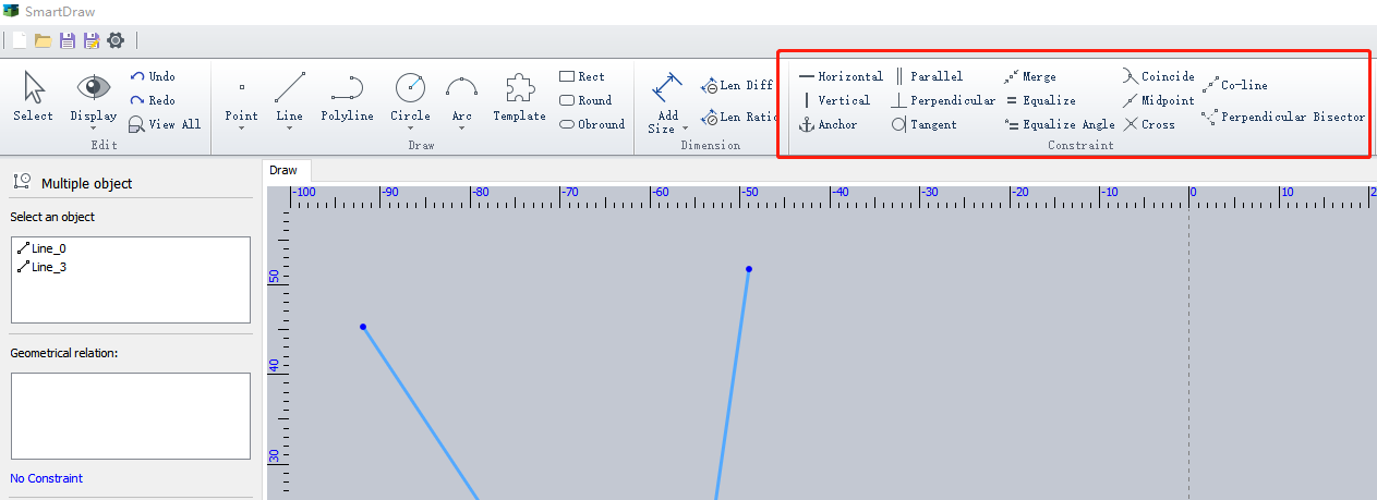
To add constraints by selecting shapes, first activate the constraint command and then select the shape objects.
This means that you should first activate a specific constraint command from the "Constraint Settings", and then click on the shape objects to which you want to apply the constraint.
For example, in the following figure, click "Perpendicular Bisector" first, and then click points 1, 2, and 3 in sequence (the middle point must be clicked first) to apply the "Perpendicular Bisector" constraint relationship.
This method involves selecting shapes in groups.
For example, to set three lines to be parallel to each other, first activate the "Parallel" command. After clicking on lines 1 and 2, one constraint command (lines 1 and 2 are parallel) is completed and the command object is cleared.
Then, immediately click on line 3, you will find that line 3 is not parallel to lines 1 and 2. This is because there is only one object at this time, line 3, and you must click line 1 again to make lines 1 and 3 parallel.
Definition of Geometric Constraints
| Geometric Constraint | Definition |
|
Parallel Perpendicular |
Applicable to lines and points. |
| Fixed | For points, it is a fixed position; for lines, it is a fixed slope; for circles, it is a fixed radius. |
| Coincident | Two points share the same location. |
| Collinear | Points or entities lie on the same straight line. |
| Equal Angle | Two lines or linear entities are at the same angle. |
| Perpendicular Bisector | A line that divides a line segment into two equal parts and also intersects the line at a right angle (90 degrees) |
Tips
1. Clicking on the label of a geometric constraint will highlight the shape(s) associated with that constraint.
2.Clicking on the label of a selected geometric constraint and pressing the delete key will remove that constraint relationship.
3.Clicking on a shape will display all of its constraints in the information bar on the left-hand side. You can view or delete constraint relationships from the right-click context menu of a constraint.
4.In the "Display" menu, you can hide individual or all labels.
5.When there are redundant constraints, the label will turn yellow, but it does not affect the generation of the shape's extrusion feature. When there are conflicting constraints, a pop-up dialog will appear, and it is not allowed to add conflicting constraints.
What is geometric constraints?
The various shapes in a 2D sketch are interrelated and form geometric constraints, which are called geometric constraints.
For example, two lines being "perpendicular" or two circles being "equal" are considered geometric constraints. These constraints can be added to a 2D sketch using drawing tools, to ensure that the shapes in the sketch satisfy specific geometric relationships.
Geometric constraints are very important in CAD software, as they help designers to quickly create accurate and consistent sketches, and can automatically update the sketch shapes to ensure they always satisfy the specified geometric constraints. This improves design efficiency and accuracy, and reduces the likelihood of errors and repetitive work.
How to add geometric constraints in SmartDraw?
Below are three ways to add geometric constraints in SmartDraw.
1.Auto add constraints when drawing a geometry
When drawing a geometry, its geometric constraints will be automatically added based on shape capturing or drawing tool properties.
For example, when using the "Parallel Lines" command to draw parallel lines, the "Parallel" constraint relationship will be automatically generated.
2.Add constraints after selecting a geometry
Select multiple graphics (hold Shift to select) first, and then set the constraints between graphics in the left information bar.
3.Click Constraints Then Select Geometry
To add constraints by selecting shapes, first activate the constraint command and then select the shape objects.
This means that you should first activate a specific constraint command from the "Constraint Settings", and then click on the shape objects to which you want to apply the constraint.
For example, in the following figure, click "Perpendicular Bisector" first, and then click points 1, 2, and 3 in sequence (the middle point must be clicked first) to apply the "Perpendicular Bisector" constraint relationship.
This method involves selecting shapes in groups.
For example, to set three lines to be parallel to each other, first activate the "Parallel" command. After clicking on lines 1 and 2, one constraint command (lines 1 and 2 are parallel) is completed and the command object is cleared.
Then, immediately click on line 3, you will find that line 3 is not parallel to lines 1 and 2. This is because there is only one object at this time, line 3, and you must click line 1 again to make lines 1 and 3 parallel.
Definition of Geometric Constraints
| Geometric Constraint | Definition |
|
Parallel Perpendicular |
Applicable to lines and points. |
| Fixed | For points, it is a fixed position; for lines, it is a fixed slope; for circles, it is a fixed radius. |
| Coincident | Two points share the same location. |
| Collinear | Points or entities lie on the same straight line. |
| Equal Angle | Two lines or linear entities are at the same angle. |
| Perpendicular Bisector | A line that divides a line segment into two equal parts and also intersects the line at a right angle (90 degrees) |
Tips
1. Clicking on the label of a geometric constraint will highlight the shape(s) associated with that constraint.
2.Clicking on the label of a selected geometric constraint and pressing the delete key will remove that constraint relationship.
3.Clicking on a shape will display all of its constraints in the information bar on the left-hand side. You can view or delete constraint relationships from the right-click context menu of a constraint.
4.In the "Display" menu, you can hide individual or all labels.
5.When there are redundant constraints, the label will turn yellow, but it does not affect the generation of the shape's extrusion feature. When there are conflicting constraints, a pop-up dialog will appear, and it is not allowed to add conflicting constraints.

