

-
Products
Overview Products

-
2D Cutting
-
Tube Cutting
-
3D Cutting
-
Intelligent Welding
-
Intelligent Cutting Head
-
Industrial Automation
-
Industrial Software
-
Combination
-
Combination
BOCHU New Product -
Combination
BOCHU New Product -
BOCHU New Product
-
2D Cutting Head
Tube Cutting Head
3D Cutting Head
Consumables
BOCHU New Product -
Servo
BOCHU New Product -
Industrial 4.0
-
- Support
- About
- Online Store


.png)


- Software Download
- Manual
- Video
- Tutorial
Machine Axis
Open machine config tool  , under 'Machine' page is where to setup motion axes and mechanic error compensation. CypCut supports 4 servo axes
which are X/Y1/Y2/W shown in image below(vertical Z axis controlled by BCS100 height controller), Y1 and Y2 send synchronous command, W can be assigned to control auto focus
motor or rotary axis motor. CypCut send pulse and positive/negative signal for motion control, the right setting in this page is crucial for machine to execute accurate motion command
also result in other functions like detect workpiece edge, fly cut and return origin.
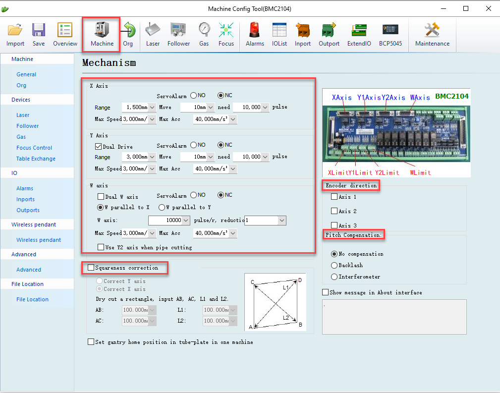
Axis Setting
Range set by actual machine travel range, which works in software limit protection and white frame in CypCut drawing board. The change of 'range' value will also result in the
white box dimension on drawing board.
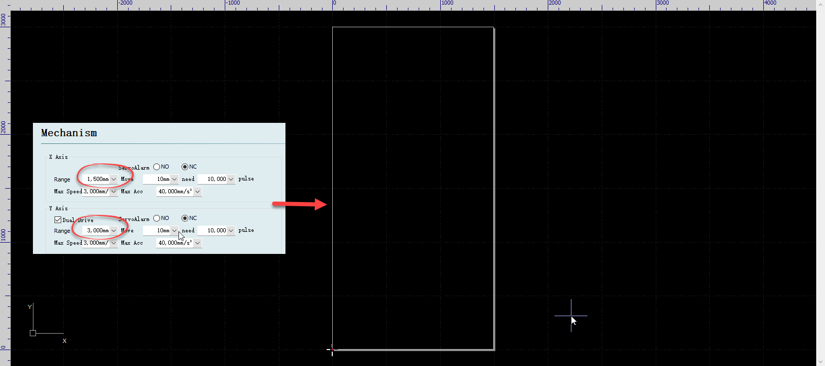
Pulse output set by the equivalent of pulse output per millimeter liner distance on the machine load and pulse required by servo driver per revolution. Setup move 10mm need 10000
pulses as an example here, it means controller will send motor driver 10000 pulses to run 10mm liner distance on machine load.
Max speed and max acceleration set by maximum machine speed and acceleration to reach.
Servo alarm set as NO or NC depends on triggered polarity of servo alarm is normal-open or normal-close.
For Y axes, if use dual-drive, please select 'Dual-drive' option.
Encoder Direction
Encoder direction is to define pulse direction from encoder feedback. You can run an encoder analysis test in CypCut File>Diagnostic Tool > Card Monitor to check the pulse
and direction setting. Under below image, the test result shows the pulse direction from Y driver is opposite, in this case uncheck the axis2,3 option to reverse the pulse direction.
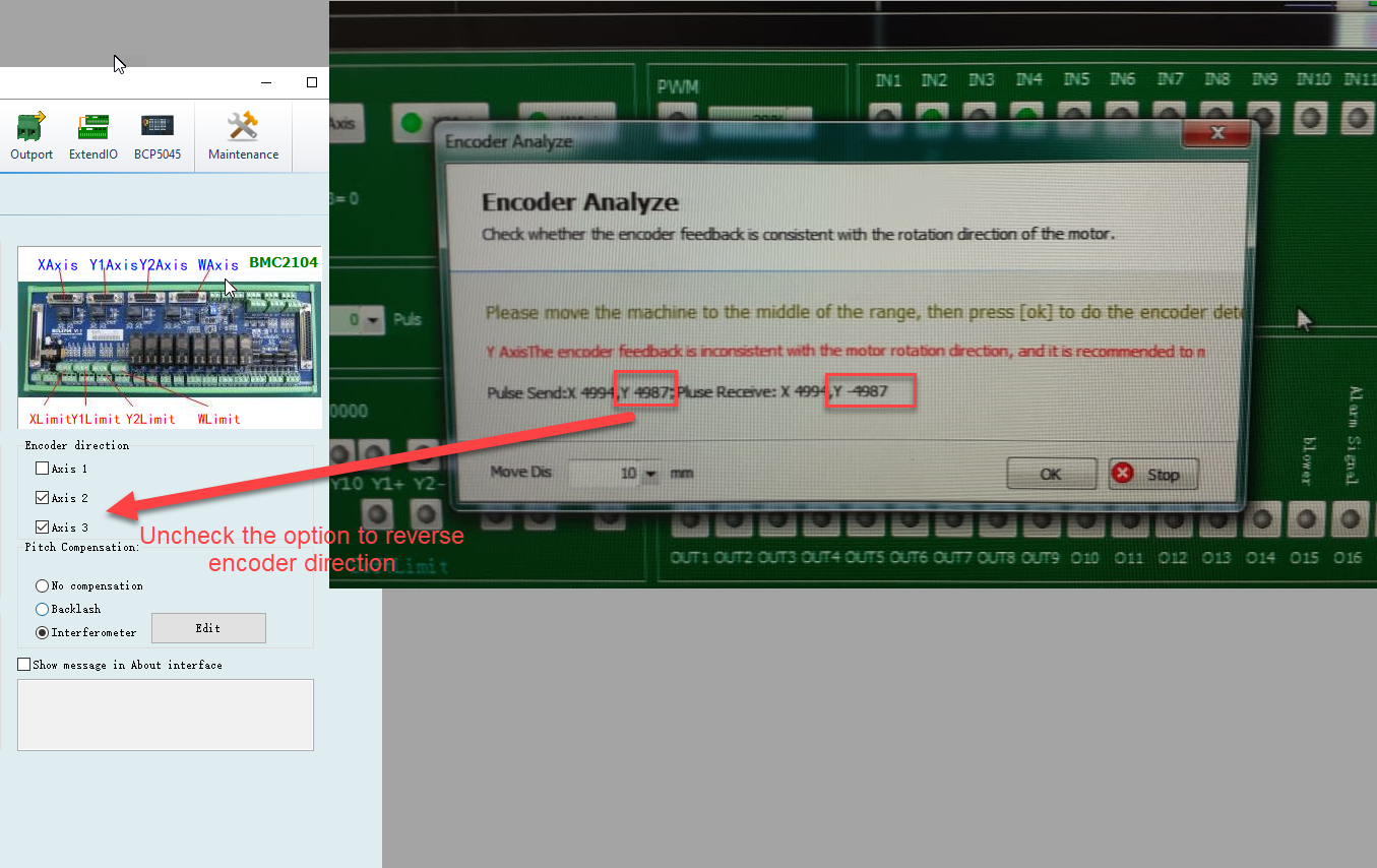
Notice: this direction only for controller to define feedback pulse direction, doesn't change motor rotation direction.
Pitch Error Compensation
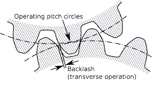
Backlash is a natural existence in gear rack mechanism which will cause a idle running in machine load when involved in motor direction change.
For higher precision compensation you can import full measured pitch error data from interferometer or other measurement instrument.
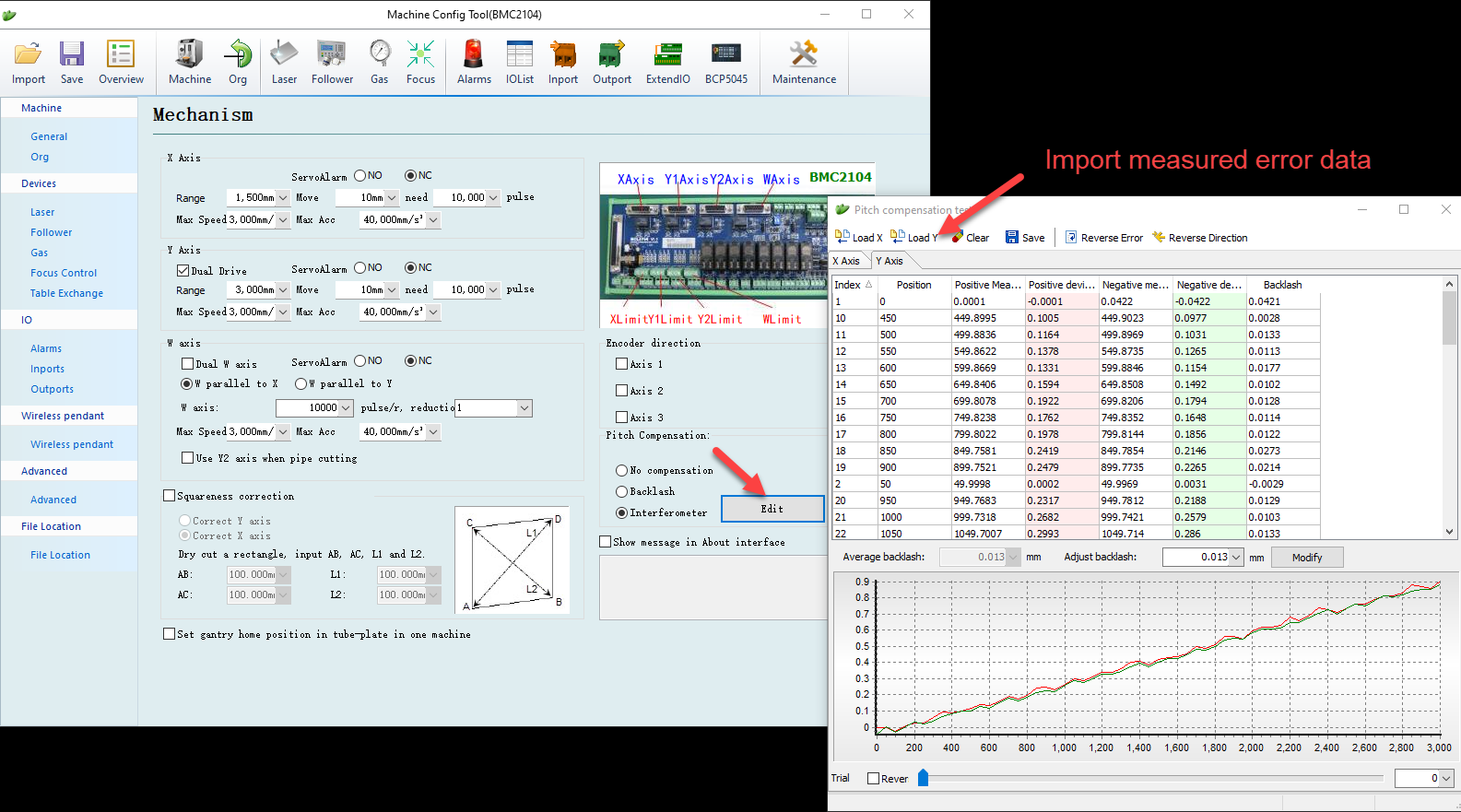
See related article in pitch error measurement
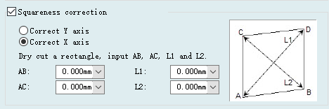
Squareness Correction
Squareness correction applied to compensation when X and Y axis not orthogonal vertical that machine frame distorted after long time usage and impact. The operation is to cut
a square about 1m*1m and input measured value of each edge required.
Machine Axis
Open machine config tool , under 'Machine' page is where to setup motion axes and mechanic error compensation. CypCut supports 4 servo axes
which are X/Y1/Y2/W shown in image below(vertical Z axis controlled by BCS100 height controller), Y1 and Y2 send synchronous command, W can be assigned to control auto focus
motor or rotary axis motor. CypCut send pulse and positive/negative signal for motion control, the right setting in this page is crucial for machine to execute accurate motion command
also result in other functions like detect workpiece edge, fly cut and return origin.
Axis Setting
Range set by actual machine travel range, which works in software limit protection and white frame in CypCut drawing board. The change of 'range' value will also result in the
white box dimension on drawing board.
Pulse output set by the equivalent of pulse output per millimeter liner distance on the machine load and pulse required by servo driver per revolution. Setup move 10mm need 10000
pulses as an example here, it means controller will send motor driver 10000 pulses to run 10mm liner distance on machine load.
Max speed and max acceleration set by maximum machine speed and acceleration to reach.
Servo alarm set as NO or NC depends on triggered polarity of servo alarm is normal-open or normal-close.
For Y axes, if use dual-drive, please select 'Dual-drive' option.
Encoder Direction
Encoder direction is to define pulse direction from encoder feedback. You can run an encoder analysis test in CypCut File>Diagnostic Tool > Card Monitor to check the pulse
and direction setting. Under below image, the test result shows the pulse direction from Y driver is opposite, in this case uncheck the axis2,3 option to reverse the pulse direction.
Notice: this direction only for controller to define feedback pulse direction, doesn't change motor rotation direction.
Pitch Error Compensation
Backlash is a natural existence in gear rack mechanism which will cause a idle running in machine load when involved in motor direction change.
For higher precision compensation you can import full measured pitch error data from interferometer or other measurement instrument.
See related article in pitch error measurement
Squareness Correction
Squareness correction applied to compensation when X and Y axis not orthogonal vertical that machine frame distorted after long time usage and impact. The operation is to cut
a square about 1m*1m and input measured value of each edge required.

