

-
Products
Overview Products

-
2D Cutting
-
Tube Cutting
-
3D Cutting
-
Intelligent Welding
-
Intelligent Cutting Head
-
Industrial Automation
-
Industrial Software
-
Combination
-
Combination
BOCHU New Product -
Combination
BOCHU New Product -
Controller
BOCHU New Product -
2D Cutting Head
Tube Cutting Head
3D Cutting Head
Consumables
BOCHU New Product -
Servo
BOCHU New Product -
Industrial 4.0
-
- Support
- About
- Online Store


- Software Download
- Manual
- Video
- Tutorial
Fly Cut Error
Fly Cut error usually happen in two types of scenarios described below.
Scenario 1: Missing Cutting
In normal cutting, program decides laser firing position by toolpath while in fly cutting laser firing position based on both toolpath and pulse feedback from encoder. If pulse
feedback from encoder go wrong in numbers or polarity, laser firing in fly cutting will go wrong and you can see missing cutting or laser firing at travel path.
Troubleshooting Steps:
Run a 'Encoder analyze' test in CypCut File > Diagnosis Tool > Card Monitor. And check the test result see which case listed below meets your situation and follow the operation
guide.

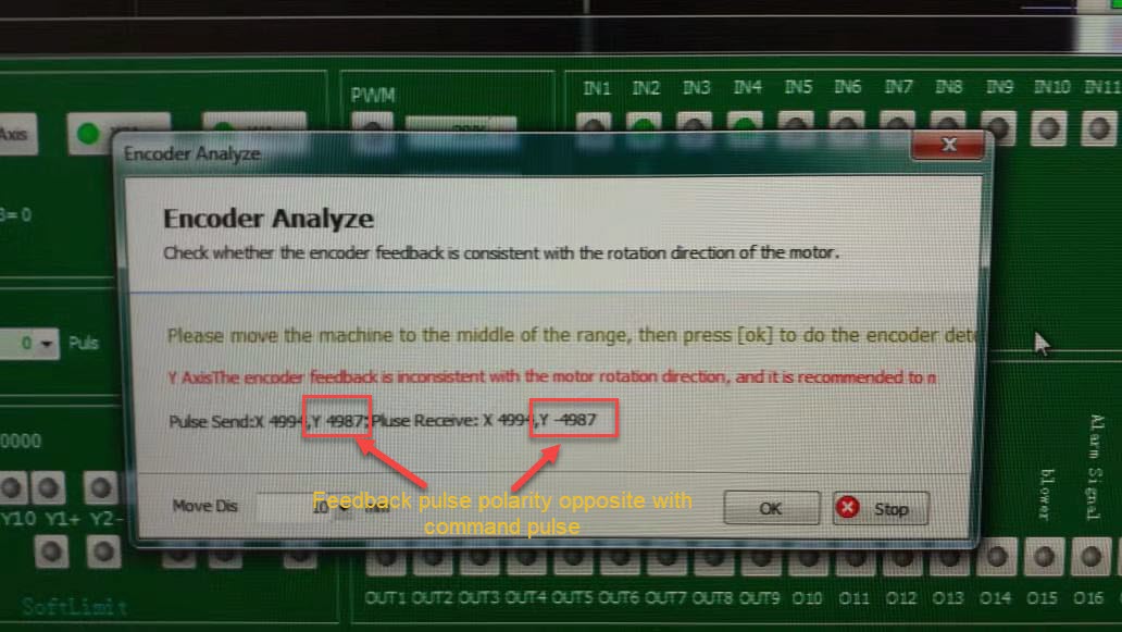
Case 1. Received pulse polarity opposite with command pulse.
In below image that feedback pulse(-4987) from Y axis opposite with command pulse(+4987). You need to reverse pulse polarity in CypCut 'Machine Config Tool'.
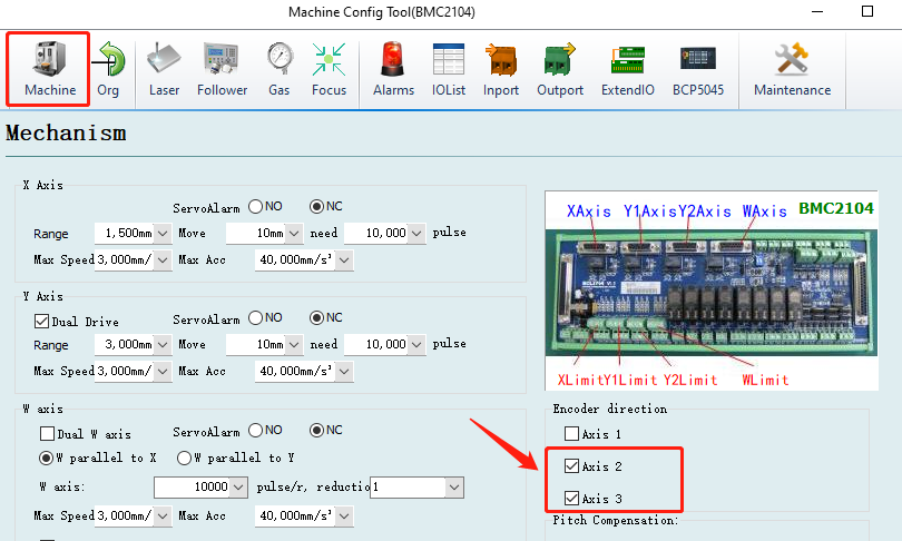
Check/uncheck the 'encoder direction' option to reverse the pulse polarity. For Y axis, you need to change axis2/3, for X axis it's axis 1. This modification doesn't change motor
rotation direction. Save the setting and run a test in CypCut card monitor again and confirm test result goes right.
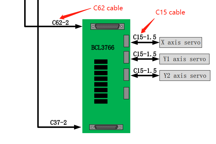
Notice: if change the 'encoder direction' setting in machine config but encoder analyze result still remains same that pulse polarity is opposite, please check C15-pin cable plug
welding and signal pin of C62 cable to confirm it's in normal condition.
Case 2 Received pulse numbers doesn't match with command pulse numbers.
1.Check the setting(pulse output per motor revolution) in servo driver if matches with the pulse setting in CypCut machine config tool.
2.Check the signal pin of C15 cable plug if in solid welding, and signal pin of C62 cable plug to confirm it in normal condition.
3.The last operation is to change another BMC control card and check if 'encoder analyze' result turns right.
Case 3 Doesn't Receive Pulse From Encoder.
1.Check the signal pin of C15 cable plug if in solid welding, and signal pin of C62 cable plug to confirm it in normal condition.
2.The last operation is to change another BMC control card and check if receive any pulses from encoder.
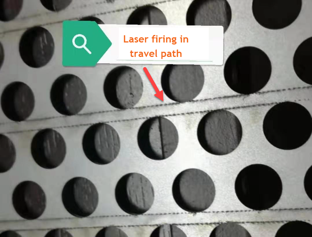
Scenario 2: Laser Firing in Travel Path
The other scenario of fly cut error is laser firing in travel path like the phenomenon in below image.
Troubleshooting Steps:
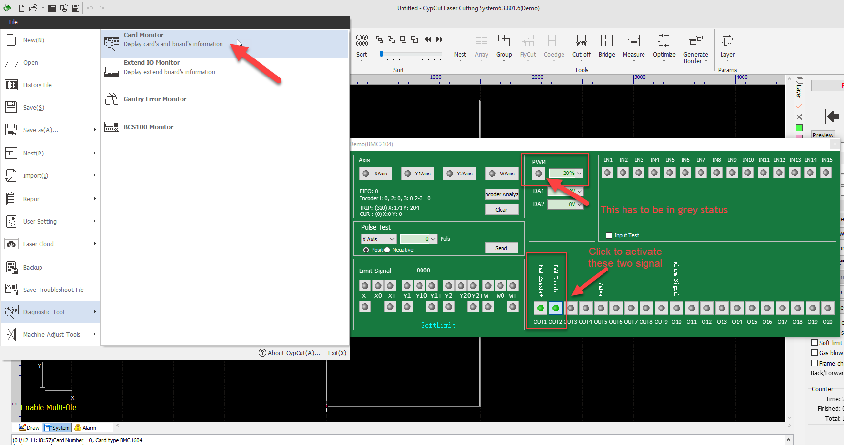
Step 1: Open card monitor in CypCut File > Diagnosis Tool. Activate PWM+/- signal pin(if configured) in below image, and make sure PWM output in grey color.
Step 2: Measure voltage at P+/- signal pin and observe the measured value. This is to check if it's laser leakage out of false signal from laser source interference.
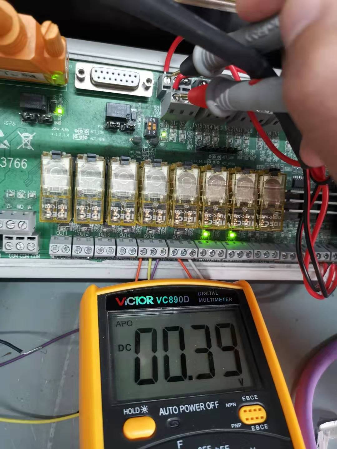
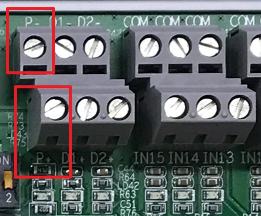
If measured value is not zero, you need to take off the signal cable in P+ and P-, then measure again. If voltage turns zero after pulled off cable in P+/-, you need to:
1.Check and confirm laser source is well grounded.
2.Change modulation cable with better shielding layer.
3.If problem still exists, connect a resistance of 1000Ω between P+ and P- in parallel.
If voltage still not zero after pulled off cable in P+/-, contact FSCUT support.
If measured value is zero, it means laser firing without command signal from controller, you need to contact laser source supplier for trouble-shooting.
- Related article: 'Create Fly Cut Toolpath'
Fly Cut Error
Fly Cut error usually happen in two types of scenarios described below.
Scenario 1: Missing Cutting
In normal cutting, program decides laser firing position by toolpath while in fly cutting laser firing position based on both toolpath and pulse feedback from encoder. If pulse
feedback from encoder go wrong in numbers or polarity, laser firing in fly cutting will go wrong and you can see missing cutting or laser firing at travel path.
Troubleshooting Steps:
Run a 'Encoder analyze' test in CypCut File > Diagnosis Tool > Card Monitor. And check the test result see which case listed below meets your situation and follow the operation
guide.
Case 1. Received pulse polarity opposite with command pulse.
In below image that feedback pulse(-4987) from Y axis opposite with command pulse(+4987). You need to reverse pulse polarity in CypCut 'Machine Config Tool'.
Check/uncheck the 'encoder direction' option to reverse the pulse polarity. For Y axis, you need to change axis2/3, for X axis it's axis 1. This modification doesn't change motor
rotation direction. Save the setting and run a test in CypCut card monitor again and confirm test result goes right.
Notice: if change the 'encoder direction' setting in machine config but encoder analyze result still remains same that pulse polarity is opposite, please check C15-pin cable plug
welding and signal pin of C62 cable to confirm it's in normal condition.
Case 2 Received pulse numbers doesn't match with command pulse numbers.
1.Check the setting(pulse output per motor revolution) in servo driver if matches with the pulse setting in CypCut machine config tool.
2.Check the signal pin of C15 cable plug if in solid welding, and signal pin of C62 cable plug to confirm it in normal condition.
3.The last operation is to change another BMC control card and check if 'encoder analyze' result turns right.
Case 3 Doesn't Receive Pulse From Encoder.
1.Check the signal pin of C15 cable plug if in solid welding, and signal pin of C62 cable plug to confirm it in normal condition.
2.The last operation is to change another BMC control card and check if receive any pulses from encoder.
Scenario 2: Laser Firing in Travel Path
The other scenario of fly cut error is laser firing in travel path like the phenomenon in below image.
Troubleshooting Steps:
Step 1: Open card monitor in CypCut File > Diagnosis Tool. Activate PWM+/- signal pin(if configured) in below image, and make sure PWM output in grey color.
Step 2: Measure voltage at P+/- signal pin and observe the measured value. This is to check if it's laser leakage out of false signal from laser source interference.
If measured value is not zero, you need to take off the signal cable in P+ and P-, then measure again. If voltage turns zero after pulled off cable in P+/-, you need to:
1.Check and confirm laser source is well grounded.
2.Change modulation cable with better shielding layer.
3.If problem still exists, connect a resistance of 1000Ω between P+ and P- in parallel.
If voltage still not zero after pulled off cable in P+/-, contact FSCUT support.
If measured value is zero, it means laser firing without command signal from controller, you need to contact laser source supplier for trouble-shooting.
- Related article: 'Create Fly Cut Toolpath'

